
Sensor patch, system, and method for detecting fluid leakage

a technology of sensor patch and leakage, which is applied in the direction of process and machine control, instruments, other medical devices, etc., can solve the problems of excessive blood loss, bleeding at the wound, and a long time before the caretaker or the patient notices the bleeding,

Active Publication Date: 2018-01-04
NAT TAIPEI UNIV OF TECH +1
View PDF0 Cites 6 Cited by
  • Summary
  • Abstract
  • Description
  • Claims
  • Application Information

AI Technical Summary

Benefits of technology

The present patent is about a sensor patch for detecting fluid leaks from a target site on a subject. The sensor patch has a first detecting unit and a second detecting unit with conductive wires and an insulating sheath. The sensor patch can be attached to the subject using an adhesive surface. The system also includes a wearable detection device with a power supply, processing unit, and wireless communication unit. The processing unit receives the electric signals from the sensor patch and determines the impedance of the signals. The wireless communication unit sends an alarm upon receiving the leak signal. The technical effect of this invention is to provide a simple and effective way to detect fluid leaks from a target site on a subject.

Problems solved by technology

However, the closed wounds are prone to open, leading to bleeding at the wounds.
In the case where the wounds are covered by dressings or the patients are unconscious or otherwise unable to be aware of the bleeding, it may take a long time before the caretaker or the patient notices the bleeding.
This may result in excessive blood loss, which may jeopardize the patient's recovery process.
During the period in which the syringe needle stays in the patient's body, the fluid being delivered or withdrawn may leak from the patient's vein or the mispositioned needle, or the tissue surrounding the needle may bleed.
The leaked fluid, if not attended to properly, will damage the tissue around the injection site, which is known as extravasation.
Depending on the medication, amount of exposure, and location, extravasation can potentially cause serious injury and permanent harm, such as tissue necrosis.
However, according to survey conducted by Pennsylvania Patient Safety Advisory in 2007, the alarm signal was only activated in half of the total leakage cases.

Method used


Image

  • Sensor patch, system, and method for detecting fluid leakage
  • Sensor patch, system, and method for detecting fluid leakage
  • Sensor patch, system, and method for detecting fluid leakage

Examples


example 2

[0092]In this example, the detection time and detectable liquid volume of the present sensor patch were determined. In three experimental groups, the first ends of the paired sensors (spaced by 5 mm) were respectively disposed above (Group 1), without (Group 2), and under (Group 3) an additional highly permeable adhesive bandage (n=3). Thereafter, the blood was slowly injected to the target site in close proximity to the first ends of the paired sensors with a needle until an alarm was given by the alarm device. The volume of blood injected when the alarm went off and time elapsed since the injection started were summarized in Table 2.

TABLE 2Group 1Group 2Group 3Test 1 35 sec.  1 sec.  3 sec.3.3 c.c.0.14 c.c.1.2 c.c.Test 2 38 sec.  1 sec.  3 sec.3.5 c.c.0.15 c.c.1.1 c.c.Test 3 33 sec.  1 sec.  3 sec.3.3 c.c.0.17 c.c.1.4 c.c.

[0093]The data in Table 2 indicated that when the paired sensors were disposed above the adhesive bandage (Group 1), the present wearable detection device could ...

example 3

[0094]In the present example, one sensor pair was used to determine the impedance of different liquid (0.5 mL) on the body surface of a human subject. The experimental results indicated that the impedance of the blood was 520 KO, the impedance of 200 mg / mL glucose solution was 550 KO, the impedance of sweat was 160 KO, and the impedance of saline was 360 KO. The results were used as the basis for the design of the bridge circuit. In the following experiments, the threshold impedance value of the bridge circuit was 100 KO.

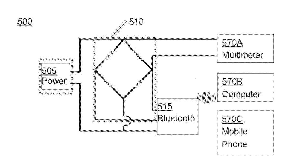
[0095]Thereafter, the wearable detection device 500 illustrated in FIG. 5 and two sensor pairs were used to detect the leakage of various liquids. As illustrated in FIG. 5, the wearable detection device 500 comprises a power 505 (3 V), a bridge circuit 510 and a Bluetooth module 515. The wearable detection device 500 can be coupled with various alarm device; for example, the wearable detection device 500 can be electrically coupled with a multimeter 570A (such as a ...

example 4

[0098]In this example, the wearable detection device 500 described in the Example 3, above, was used together with two sensor pairs in which the first ends of the respective sensor pairs were in direct contact with the skin of the subject, and the distance between the first and second locations of the two sensor pairs was 5 millimeters. Thereafter, the various liquids (blood, 200 mg / mL glucose solution and saline) and sweat were respectively injected into the sites in close proximity to the first and second locations of the first and second sensor pairs using a needle; the injected volume that triggered the alarm was recorded, and the results are summarized in Table 4.

TABLE 4Group 1Group 2Group 3Blood / SweatGlucose Sol. / SweatSaline / SweatTest 1  1 sec.  1 sec.  1 sec.0.2 c.c.0.2 c.c.0.2 c.c.Test 2  1 sec.  1 sec.  1 sec.0.2 c.c.0.2 c.c.0.2 c.c.Test 3  1 sec.  1 sec.  1 sec.0.2 c.c.0.2 c.c.0.2 c.c.

[0099]The data in Table 4 indicated that the present system for detecting fluid leakage w...


PUM


Abstract

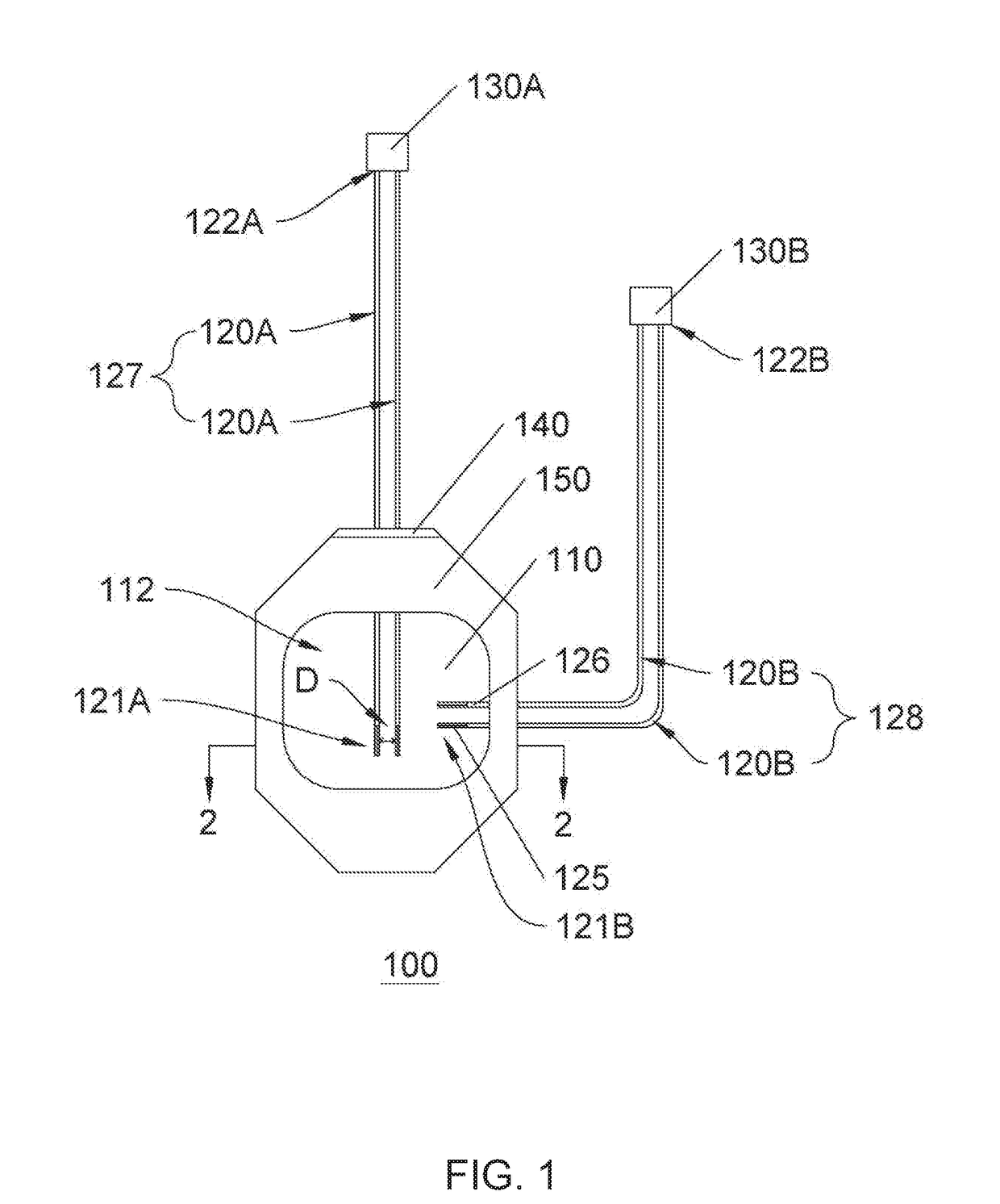
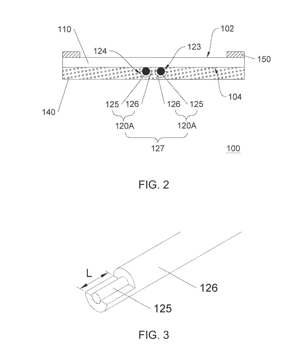
A sensor patch, system, and method for detecting a fluid leaked from a target site of a subject are provided. The sensor patch (100) includes a first detecting unit (127), a second detecting unit (128), and a patch body (110). The first detecting unit (127) includes a first pair of sensors (120A) respectively having a first end (121A) configured to be placed approximating the target site, while the second detecting unit (128) includes a second pair of sensors (120B) respectively having a first end (121B) configured to be placed away from the target site. Each sensor includes a conductive wire (125) and an insulating sheath (126) encapsulating the conductive wire (125) in a manner that a portion of the first end (121A, 121B) of the conductive wire (125) is exposed yet without directly contacting the subject's skin. The patch body (110) has an adhesive surface (104) for securing the first and second detecting units (127, 128) to the subject. The sensor patch enhances the detection specificity.

Description

BACKGROUND OF THE INVENTION1. Field of the Invention[0001]The present disclosure relates to the detection of fluid leakage occurring at a target site of a subject. More particularly, the disclosed invention relates to a sensor patch, system, and method for detecting said fluid leakage.2. Description of Related Art[0002]Wounds caused by surgical procedures or traumas are often stitched or closed by other means. However, the closed wounds are prone to open, leading to bleeding at the wounds. In the case where the wounds are covered by dressings or the patients are unconscious or otherwise unable to be aware of the bleeding, it may take a long time before the caretaker or the patient notices the bleeding. This may result in excessive blood loss, which may jeopardize the patient's recovery process.[0003]Moreover, in the clinical setting, procedures for the injection of fluid into the human body and the withdrawal of body fluid from the human body are quite common. For example, medicines...

Claims


Application Information

Patent Timeline
IPC IPC(8): A61M5/168A61M5/142
CPCA61M5/16831A61M5/14248A61M2205/15A61M1/3656
Inventor WU, CHIH-JENHUANG, JUNG-TANG
Owner NAT TAIPEI UNIV OF TECH
Learn More