Subsea carrier

a technology for submerged ships and ships, applied in waterborne vessels, special-purpose vessels, vessel parts, etc., can solve the problems of significantly reducing design requirements, reduce operating costs, reduce buoyancy, and reduce drag. effect of

Inactive Publication Date: 2018-01-04
SUBHYDRO
View PDF1 Cites 3 Cited by
  • Summary
  • Abstract
  • Description
  • Claims
  • Application Information

AI Technical Summary

Benefits of technology

[0022]The first connector is primarily movable in a longitudinal direction in order to adjust the pitch of the main body. The pitch should be adjusted such that the main body presents a minimum area perpendicular to the direction of travel at all times in order to minimise drag and thus operational costs. Equally important, e.g. a positive pitch causes the main body to move upward. This is undesired because the external pressure should exceed the internal pressure in order to compress the structure. The first connector may also be movable in a lateral direction in order to control roll, in particular at loading and unloading points.
[0023]In a preferred embodiment, the length of the stabilising cable exceeds the water depth. In this embodiment, the floating element floats on the surface, so that if the main body starts rising, the floating element rises out of the water. This reduces the buoyancy and thereby causes the main body to sink due to gravity. Opposite, if the main body starts sinking, an increased volume of the floating element is submerged. This increases the buoyancy and causes the main body to rise due to buoyancy transferred through the stabilising cable.
[0024]A preferred embodiment comprises a bridle...

Problems solved by technology

However, embodiments with a somewhat positive internal differential pressure are also anticipated because handling a limited dif...

Method used


Image

  • Subsea carrier
  • Subsea carrier
  • Subsea carrier

Examples


Embodiment Construction

[0058]The drawings are schematic and intended to illustrate the principles of the invention. Hence, the drawings are not necessarily to scale, and numerous details are omitted for clarity.

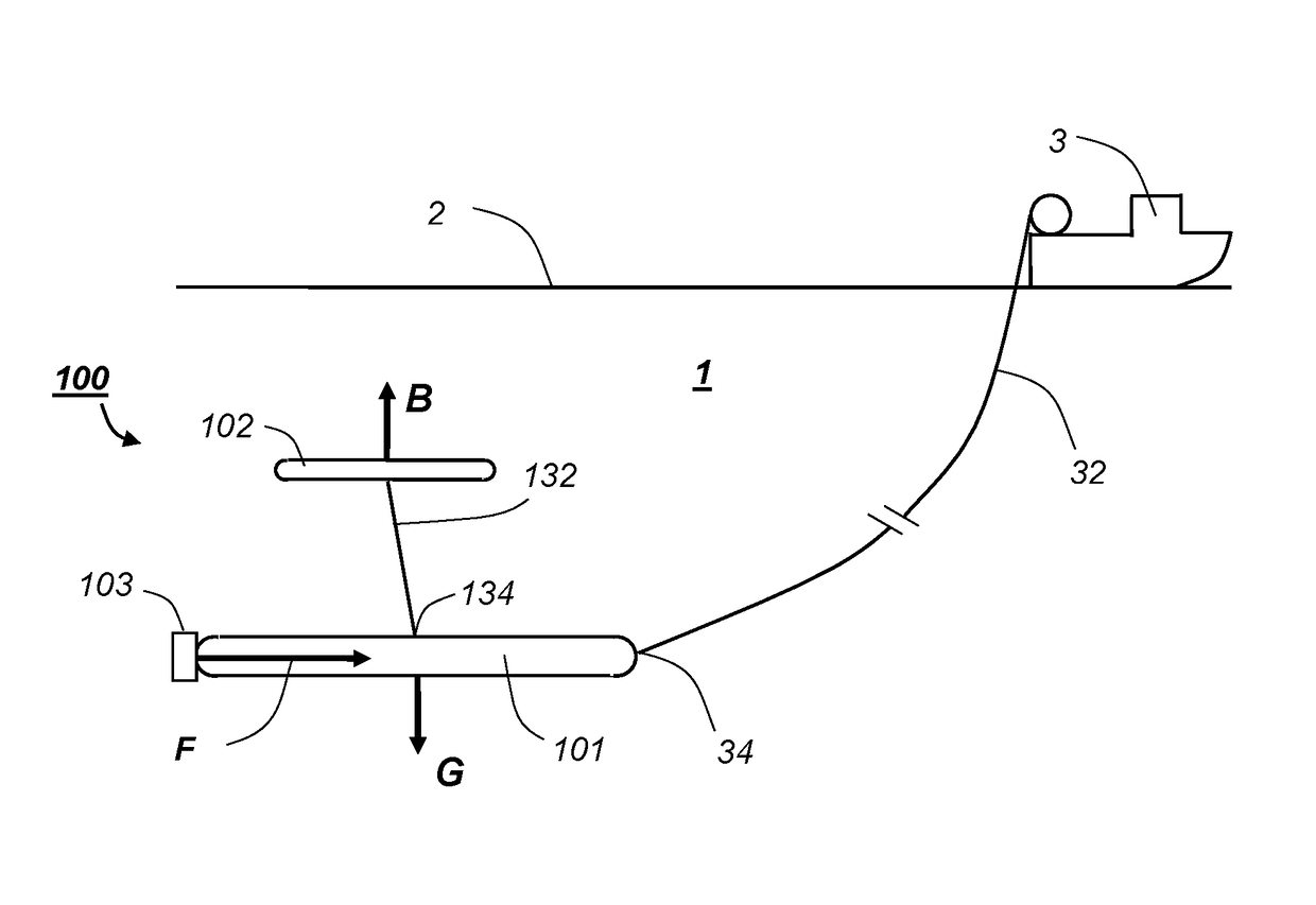
[0059]An important aim of the invention is to carry a cargo of fluid, e.g. hydrocarbons, from a loading point to an unloading point along a predefined path as inexpensively as possible. In the present context, this implies keeping an elongated main body 101 aligned with a predetermined path in three dimensions fixed to the Earth, e.g. longitude, latitude and depth, by controlling local coordinates fixed to the main body 101, e.g. roll, pitch and yaw as illustrated with reference to FIG. 9.

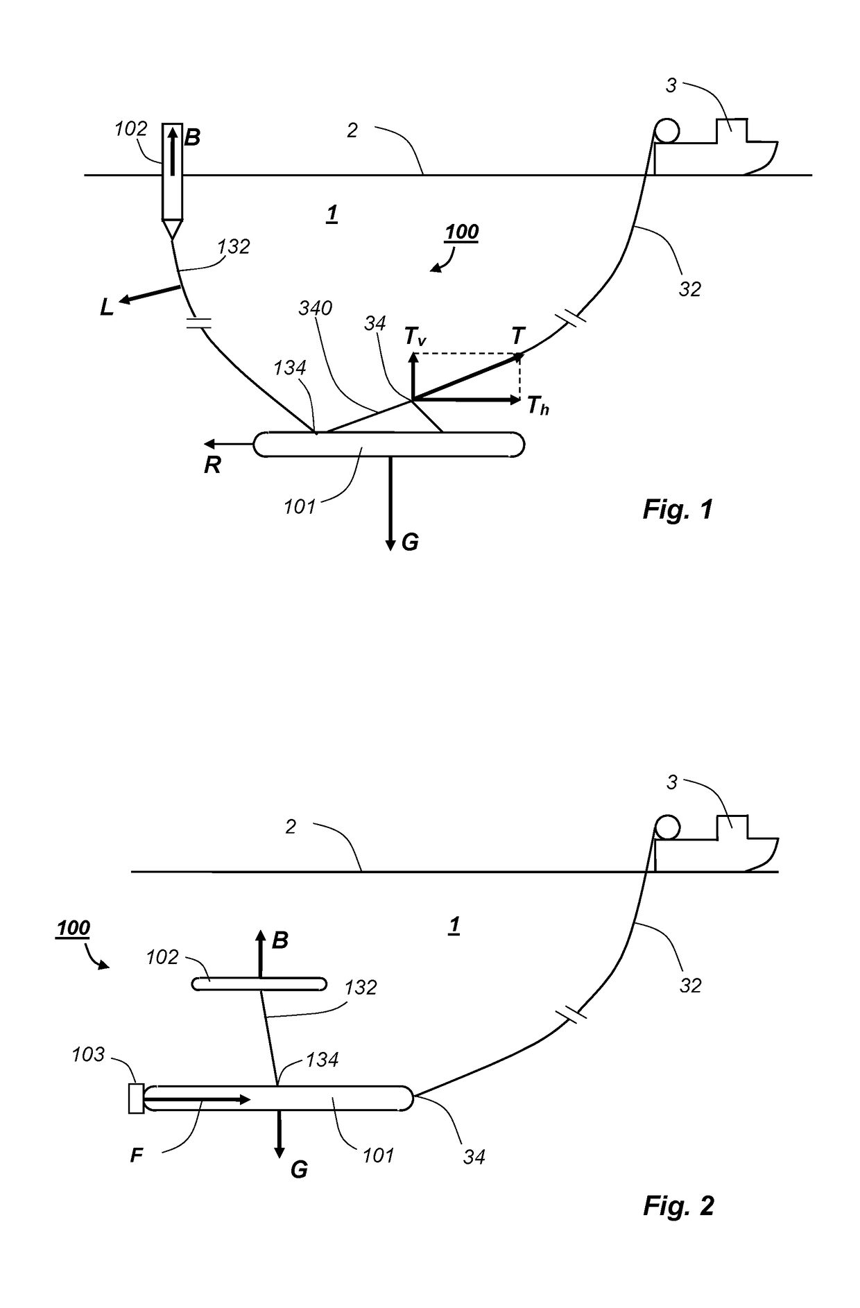
[0060]FIG. 1 illustrates a first embodiment of a system according to the invention, comprising a subsea carrier 100 partly submerged in a body of water 1 having a surface 2. A towing vessel 3 on the surface 2 tows the subsea carrier 100 by means of a towing cable 32, in the claims expressed as a control cable with...


PUM


Abstract

A subsea carrier (100) for transporting a fluid, e.g. CNG or crude, comprises a main body (101) for containing the fluid at a predetermined internal pressure, wherein the main body (101) preferably is made of concrete and designed to operate at a water depth where the external pressure substantially counteracts the internal pressure. The subsea carrier has a floating element (102) connected to the main body (101) by a stabilising cable (132), wherein the stabilising cable (132) comprises a first rope (321) for transmitting force and is attached to a first connector (134) that is movable with respect to the main body (101). A system wherein the subsea carrier is towed by a surface vessel (3) or is self-propelled and controlled remotely is also disclosed. The subsea carrier (100) reduces operational costs relative to subsea carriers with traditional control surfaces and ballasting systems at large cargo volumes, e.g. 150 000 m3 or more.

Description

BACKGROUND OF THE INVENTIONField of the Invention[0001]The present invention relates to a subsea carrier for a fluid, e.g. oil or compressed natural gas.Prior and Related Art[0002]In the following, hydrocarbons serves as an example of fluid cargo. However, embodiments of the carrier described herein can carry fresh water, inorganic gas or other fluid chemical compounds. Here, the term “hydrocarbons” means oil and gas, typically extracted from a subterranean reservoir. Natural gas, or NG, means hydrocarbons that are gaseous at normal conditions, i.e. 0° C. and 1 bar, such as methane, whereas the hydrocarbons also include components that are liquid at normal conditions, e.g. crude.[0003]Starting from a reservoir and a pressure of several hundred bar, a mixture of hydrocarbons, water and other substances, e.g. H2S, are brought to the surface under closely super-vised conditions. Temperature and pressure is controlled and chemicals may be added, e.g. to prevent or inhibit formation of h...

Claims


Application Information

Patent Timeline
IPC IPC(8): B63B21/66B63G8/14B63B3/13B63G8/22B63G8/42
CPCB63B21/66B63B3/13B63G8/22B63G8/42B63B21/663B63G8/14B63G2008/425
Inventor SCHRAMM, RAINER
Owner SUBHYDRO
Why Eureka
Try Eureka