Method and system for improving boiler effectiveness

a technology of boiler effectiveness and boiler efficiency, applied in the field of methods and systems, can solve the problems of inability to realize the full potential of increased aph efficiency available, difficult to create dry flue gas stream, and less efficient wet esp. the effect of steam generator system

Active Publication Date: 2018-01-11
ARVOS LJUNGSTROM LLC
View PDF18 Cites 8 Cited by
  • Summary
  • Abstract
  • Description
  • Claims
  • Application Information

AI Technical Summary

Benefits of technology

[0041]There is further disclosed herein a method for retrofitting a steam generator system for improved effectiveness. The method includes removing one or more heat exchangers positioned downstream of the air preheater and reconfiguring an air supply source to the air preheater to supply a first amount of air in excess of that required for combustion of fuel in the steam generator vessel. The method also includes reconfiguring one or more of the air supply source and the air preheater such that the first amount of air is provided at a mass flow sufficient to establish a first temperature of a flue gas mixture exiting the air preheater. The first temperature is of a magnitude such that the air preheater has a cold end metal temperature that is no less than a water dew point temperature in the air preheater and such that the cold end metal temperature is less than a sulfuric acid dew point temperature. The first temperature is from about 105° C. (220° F.) to about 125° C. (257° F.). The method includes providing SO3 mitigation in communication with the steam generator vessel. The SO3 mitigation is configured to mitigate the SO3 in the flue gas mixture generated in the steam generator vessel. The mitigating of SO3 occurs before the flue gas mixture enters the air preheater. The method includes configuring the air preheater to heat the first amount of air to a second temperature which is substantially no less than the temperature of combustion air of an original system and being about of 288° C. to 399° C. (550° F. to 750° F.) to maintain or improve boiler efficiency. The method includes supplying a first portion of the first amount of air to the steam generator vessel for combustion of the fuel. The method further includes discharging the flue gas mixture at the first temperature, directly from the air preheater to the particulate collection system, thereby removing particulate from the flue gas mixture and creating a first treated flue gas mixture. The method also includes, discharging the first treated flue gas mixture from the particulate removal system directly into the flue gas desulfurization system thereby creating in and discharging from the flue gas desulfurization system, a second treated flue gas mixture at a third temperature, for example, but not limited to 52° C. to about 60° C. (125° F. to 140° F.). The method includes injecting a second portion of the first amount of air as flue gas reheat air fed from the air preheater at the second temperature with the second flue treated flue gas mixture at the third temperature, thereby creating third treated flue gas mixture at a fourth temperature (e.g., at least about 68° C. (155° F.)), prior to entering the discharge stack. The method also includes, admitting the third treated flue gas mixture to the discharge stack at the fourth temperature. The third temperature is of a magnitude sufficient to allow the flue gas reheat air to raise the fourth temperature to a magnitude sufficient to mitigate visible plume exiting the discharge stack and to mitigate corrosion in the discharge stack.

Problems solved by technology

However, those skilled in the relevant art have not been able to realize the full potential of increased APH efficiency available through the use of higher efficiency heat transfer elements and greater heat transfer area of the heat transfer elements, because of operation limitations relating to the control of pollutants, as described herein.
Creating a dry flue gas stream can be difficult because as the flue gas temperature decreases below the dew point of SO3 at a cold-end of the APH, condensation can occur, thereby causing SO3 to form H2SO4 and a relatively wet flue gas.
Moreover, if the flue gas contains the H2SO4 mist, then the less efficient wet ESP is typically employed to remove the H2SO4.
In addition, the ESPs tend to experience dust fouling (e.g., an undesirable accumulation of fly ash on ESP collector plates and removal troughs) when the temperature of the flue gas is high (e.g., 130° C. or greater).
One operational limitation of the FGD systems is the flue gas exiting the SO2 absorber can be highly corrosive to any downstream equipment such as fans, ducts, and stacks.
Another operational limitation of the FGD systems is that the SO2 absorbers require a substantial water supply and sorbent regeneration equipment.
One operational limitation relating to APH's is that employing heat transfer elements with increased heat transfer efficiency and area can cause the flue gas temperature to decrease below the dew point of SO3 at which temperature, condensation at a cold-end of the APH can occur.
This inability to completely realize the full potential of increasing the efficiency of the APH therefore limits the ability to increase the thermal efficiency of the steam generator system to be increased to its full potential.
Discharge of flue gas into the stack 109 at such low temperatures tends to cause corrosion problems and a visible plume at the discharge 109B of the stack 109.

Method used


Image

  • Method and system for improving boiler effectiveness
  • Method and system for improving boiler effectiveness
  • Method and system for improving boiler effectiveness

Examples


Embodiment Construction

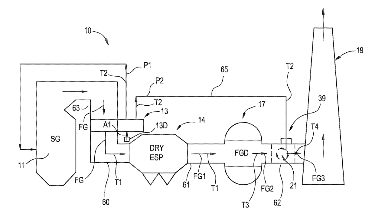
[0054]As shown in FIG. 3, a system for improving effectiveness of a steam generator system is generally designated by the numeral 10. The steam generator system 10 includes a steam generator vessel 11 and an air preheater 13 (e.g., a rotary regenerative heat exchanger). The air preheater 13 is in communication with the steam generator vessel 11 via a duct 63. The steam generator system 10 includes an air supply system 13D configured to provide air to the steam generator 11 through the air preheater 13. The steam generator system 10 also includes a particulate removal system 14, a flue gas desulfurization system 17 and a discharge stack 19 in the configuration illustrated in FIG. 3. As used herein the term “improving the effectiveness of a steam generator system” includes: 1) maintaining the overall thermal efficiency of the steam generator system 10 while eliminating heat exchangers between the air preheater 13 and the discharge stack 19; 2) reducing fouling in the air preheater 13;...


PUM


Abstract

A method for improving effectiveness of a steam generator system includes providing air to an air preheater in excess of that required for combustion of fuel and providing the air at a mass flow such that the air preheater has a cold end metal temperature that is no less than a water dew point temperature in the air preheater and such that the cold end metal temperature is less than a sulfuric acid dew point temperature. The method includes mitigating SO3 in the flue gas which is discharged directly from the air preheater to a particulate removal system and then directly into a flue gas desulfurization system. Flue gas reheat air is fed from the air preheater to heat the flue gas prior to entering a discharge stack to raise the temperature of the flue gas to mitigate visible plume exiting and to mitigate corrosion in the discharge stack.

Description

FIELD OF THE INVENTION[0001]The present invention relates generally to a method and system for improving the effectiveness of a fossil fuel fired steam generator and the effectiveness of particulate removal, and is more particularly directed to a method and system for improving the effectiveness of an air preheater by reducing fouling and improving the thermal efficiency of the fossil fuel fired steam generator and the efficiency of an electro-static precipitator by using SO3 mitigation upstream of the air preheater, excess air to the air preheater and stack gas reheat to thereby eliminate one or more heat exchangers and eliminate one or more fans downstream of the air preheater.BACKGROUND OF THE INVENTION[0002]There are many types of steam generator systems that are employed for the generation of steam for use in the generation of electricity and chemical processing plants. Some of the steam generation systems combust fossil fuel such as coal, natural gas and oil in a steam generat...

Claims


Application Information

Patent Timeline
Patent Type & Authority Applications(United States)
IPC IPC(8): F23J15/02
CPCF23J15/022F23J2217/00F23J2215/20B01D53/30B01D53/50B01D53/502F23J15/06F23J15/08F22B37/008F22B37/025F23L2900/15043F23J15/00Y02E20/34F22B37/00F22B37/02F23J15/02C02F1/10F23L15/04F23K1/04F22D1/36Y02E20/30
Inventor O'BOYLE, KEVINMATTISON, GLENN D.
Owner ARVOS LJUNGSTROM LLC
Why Eureka
Try Eureka