
Direct energy conversion assembly for nuclear fusion systems

a technology of nuclear fusion and assembly, which is applied in the direction of nuclear reactors, greenhouse gas reduction, nuclear engineering, etc., can solve the problems of large fusion device and system, large energy loss in conventional fusion system, complex, and difficult to manage, so as to reduce radiative loss, suppress radiation loss, and reduce cost

Active Publication Date: 2018-02-01
ALPHA RING INT LTD
View PDF0 Cites 1 Cited by
  • Summary
  • Abstract
  • Description
  • Claims
  • Application Information

AI Technical Summary

Benefits of technology

[0142]An advantage of the present inventions is that they effectively suppress radiation losses due to electron bremsstrahlung. Conventional fusion reactors such as tokamaks employ hot, highly ionized plasma. Electron-ion interactions, resulting in bremsstrahlung and cyclotron radiation, are a significant source of energy loss and is one of the reasons such systems have not been able to satisfy the Lawson criterion. However, the high-density, lightly ionized, and colder plasma employed in embodiments of the present inventions suppresses electron mobility and greatly reduces radiative losses.
[0143]Hydrogen atoms under high pressure compression can become liquid or solid metals, depending on the compressional forces and their states of rotation. In either the liquid or solid states, the density is many orders of magnitude higher than that in the gaseous state. The total reaction rate will be correspondingly higher according to the product of the particle densities of the two reactants.
[0144]In addition, metallic hydrogen becomes highly conductive or even a superconductor with zero resistance. This increases the overall conductivity of the entire system, lowering the resistive loss and the input energy required. Thus, the overall efficiency of such a system is greater, making it easier to attain a large Q factor and the corresponding energy gain.
[0145]Thus, it is presently theorized that as higher rotational speeds of the neutrals, such as, for example, hydrogen neutrals, are attained, these neutrals will become, or behave, in a manner like a liquid, solid, or superconductor. This form of the working material takes part in the fusion reaction, and is presently believed to be primarily located at the outer reaches of the fusion reaction chamber or zone nearer to the wall. The presence of this form of working material may greatly enhance the overall efficiency of the system.Positive Feedback
[0146]The present invention may generate particles during operation. In some cases these particles may provide benefit to the device's function. In embodiments utilizing ionized particles, the creation of ionizing radiation may further enhance additional fusion by increasing, modifying, maintaining, or improving the ionization or rotational movement of a working material or plasma. Thus, by way of example, an apparatus using a weakly ionized plasma and a rotation mechanism wherein the first working material is hydrogen, and the second working material is boron, may generate alpha particles. These particles may ionize additional hydrogen, and may impart to them rotational energy. Thus, this synergistic effect of fusion products creating additional ions may have the effect of increasing rotational energy without the need for additional energy from an external source. Further, to prevent this feature from leading to a runaway reaction, the system temperature and the feed of hydrogen are constantly monitored, and the feed of hydrogen can be adjusted accordingly to modify the number of neutrals present, and thus control the rate of reaction.
[0147]Diagnostics that monitor oscillations in current and voltages, which may be in-situ, and may be of micro or nano scales, may be placed inside the controlled fusion device, may communicate wirelessly to the data-control center through Wi-Fi channels. This arrangement allows for the direct monitoring and management of conditions within the fusion reaction zone. This will result in an efficient design of the fusion system. Further diagnostics and monitoring systems and techniques, such as temperature, spectroscopy, laser diagnostics, temperature monitoring, particle detectors, video, and others known to the art may be utilized to establish a control and monitoring system for a fusion reactor and power generation system.EXAMPLES

Problems solved by technology

The art's pursuit of the Lawson criterion, or substantially similar paradigms, has led to fusion devices and systems that are large, complex, difficult to manage, expensive, and economically unviable.
In particular, a major source of energy loss in conventional fusion systems is radiation due to electron bremsstrahlung and cyclotron motion as mobile electrons interact with ions in the hot plasma.
Because the conventional thinking holds that high temperatures and strongly ionized plasma are required, it was further believed in the art that inexpensive physical containment of the reaction was impossible.
Accordingly, methods being pursued in the art are directed to complex and expensive schemes to contain the reaction, such as those used in magnetic confinement systems (e.g., the ITER tokamak) and in inertial confinement systems (e.g., NIF laser).
Accordingly, there has been a long-standing and unfulfilled need for a controlled fusion reaction, and the clean energy and other benefits and beneficial uses that are associated with such a reaction.

Method used


Image

  • Direct energy conversion assembly for nuclear fusion systems
  • Direct energy conversion assembly for nuclear fusion systems
  • Direct energy conversion assembly for nuclear fusion systems

Examples


example 1

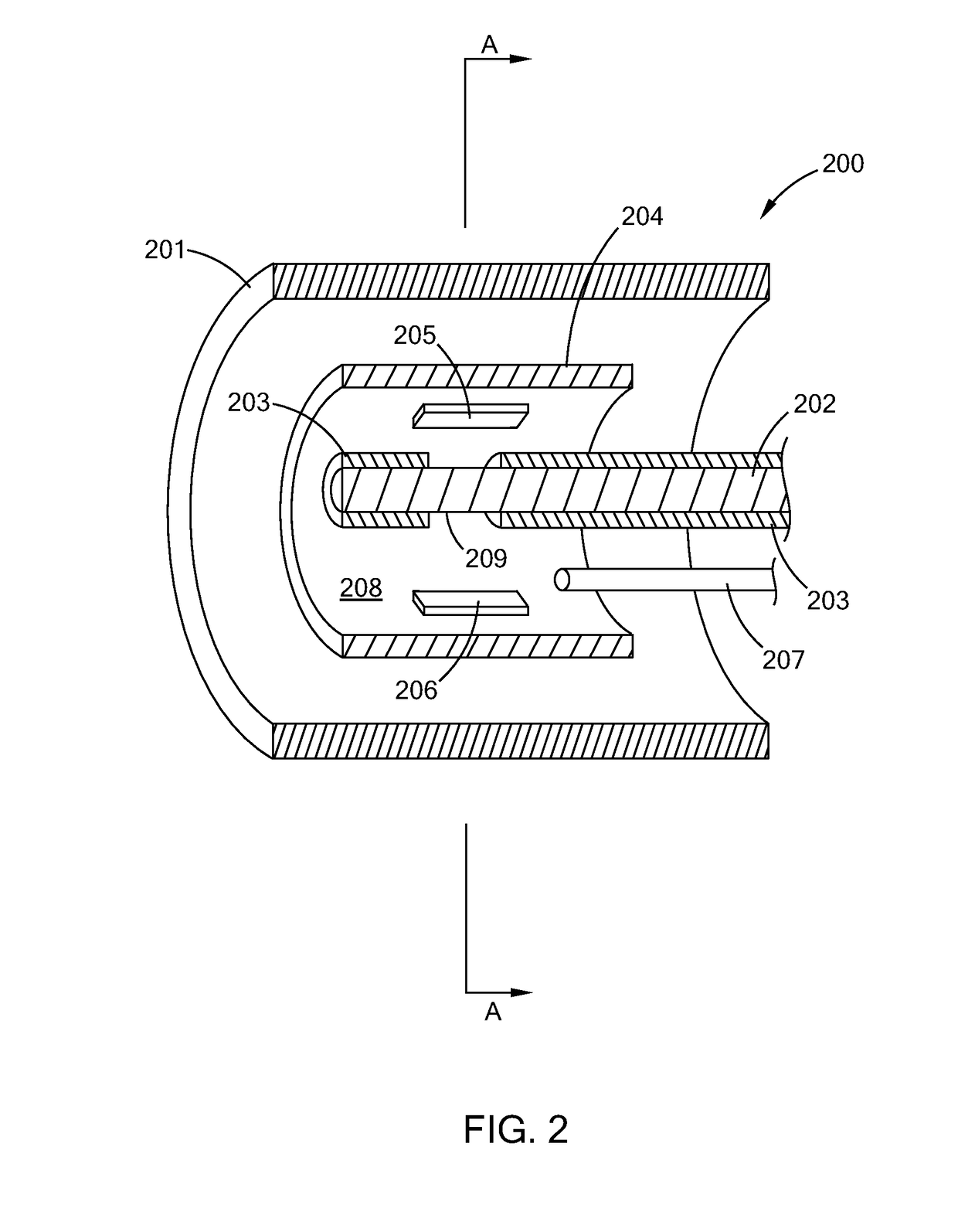
[0149]A controlled fusion device of the general type shown in the embodiment of FIG. 3, was operated to provide a controlled fusion reaction that produced high-energy alpha particles and helium. The first working material in the device is hydrogen. The second working material in the device is boron that is introduced into the device through boron nitride targets, e.g., plates, on the inner walls of the outer electrode, and a lanthanum hexaboride target, e.g., disc, that is inserted into the reaction chamber by way of a rod. The magnet provides a magnetic field of 0.5 Tesla to the internal components of the controlled fusion device. The controlled pressure chamber is purged. After purging, the controlled pressure chamber and fusion cavity are filled with hydrogen gas to about 3 torr and at ambient temperature. A voltage of about 1.4 kV is applied through a current-limiting resistor to the inner electrode, creating a plasma current of about 25 A, which imparts, due to the Lorentz forc...

example 1 (

Example 1(e)

[0159]The method and device of Example 1 is operated at a sufficient magnetic field and voltage to provide at least about 0.1 MMBtu / hour of thermal energy. This thermal energy is converted by apparatus known to those of skill in the power and electrical generation arts, such as heat exchangers, steam turbines, and electrical generators, to provide at least about 10 kW of electricity. One or more of the devices of Example 1 may be combined to provide greater thermal energy, to provide backup units should one go offline, which assembly can be associated with heat conversion devices known to those in the art.

example 2

[0160]The operation of the device along the lines of Example 1 was repeated over 400 times. Each time the evidence of the creation of helium and high energy alpha particles was observed.


PUM


Abstract

Methods, apparatuses, devices, and systems for creating, controlling, conducting, and optimizing fusion activities of nuclei. The controlled fusion activities cover a spectrum of reactions from aneutronic, fusion reactions that produce essentially no neutrons, to neutronic, fusion reactions that produce substantial numbers of neutrons.

Description

[0001]The present application: (i) claims, under 35 U.S.C. § 119(e)(1), the benefit of the filing date of Jun. 27, 2013 of U.S. provisional application Ser. No. 61 / 840,428; (ii) claims, under 35 U.S.C. § 119(e)(1), the benefit of the filing date of Jan. 8, 2014 of U.S. provisional application Ser. No. 61 / 925,114; (iii) claims, under 35 U.S.C. § 119(e)(1), the benefit of the filing date of Jan. 8, 2014 of U.S. provisional application Ser. No. 61 / 925,131; (iv) claims, under 35 U.S.C. § 119(e)(1), the benefit of the filing date of Jan. 8, 2014 of U.S. provisional application Ser. No. 61 / 925,122; (v) claims, under 35 U.S.C. § 119(e)(1), the benefit of the filing date of Jan. 8, 2014 of U.S. provisional application Ser. No. 61 / 925,148; (vi) claims, under 35 U.S.C. § 119(e)(1), the benefit of the filing date of Jan. 8, 2014 of U.S. provisional application Ser. No. 61 / 925,142; (vii) claims, under 35 U.S.C. § 119(e)(1), the benefit of the filing date of Jul. 1, 2013 of U.S. provisional appl...

Claims


Application Information

Patent Timeline
Patent Type & Authority Applications(United States)
IPC IPC(8): G21B1/05G21B3/00
CPCY02E30/126G21B1/05G21B3/006G21B1/13Y02E30/10G21B1/23
Inventor WONG, ALFRED Y.RINZLER, CHARLESWOODBURY, DAVID A.
Owner ALPHA RING INT LTD
Learn More