Multi-stage interferometer circuit with waveform shaping function

Active Publication Date: 2018-02-01
NIPPON TELEGRAPH & TELEPHONE CORP
View PDF8 Cites 45 Cited by
  • Summary
  • Abstract
  • Description
  • Claims
  • Application Information

AI Technical Summary

Benefits of technology

[0015]According to the present invention, a multi-stage interferometer circuit having a waveform-shaping optical filter function can be realized by the use of a waveguide-type technique which is inexpen

Problems solved by technology

Therefore, a total channel transmission rate can be relatively easily enhanced from the viewpoint of easiness of realization, although there is a disadvantage that a plurality of devices is required in order to parallelize a plurality of optical transmission carriers.
The method of performing Nyquist-shaping with a DSP has, first of all, a problem that the power consumption of the DSP simply increases.
On the other hand, in a high-speed DAC, the number of effective bits is approximately five, which cannot be said to be a sufficient number of bits for the purpose of waveform shaping.
Accordingly, in particular, when all of the above-descr

Method used


Image

  • Multi-stage interferometer circuit with waveform shaping function
  • Multi-stage interferometer circuit with waveform shaping function
  • Multi-stage interferometer circuit with waveform shaping function

Examples


Example

First Embodiment

[0141]FIG. 15 is a configuration diagram illustrating a multi-stage interferometer circuit 1500 according to a first embodiment of the present invention. The multi-stage interferometer circuit 1500 of FIG. 15 is an example when the number of the wavelength-multiplexed / demultiplexed channel, namely, the number of demultiplexing ports, is eight (M=8). The number of stages of interferometers is set to four (N=4), and the design parameters other than the TF are the same as the parameters given in FIG. 3.

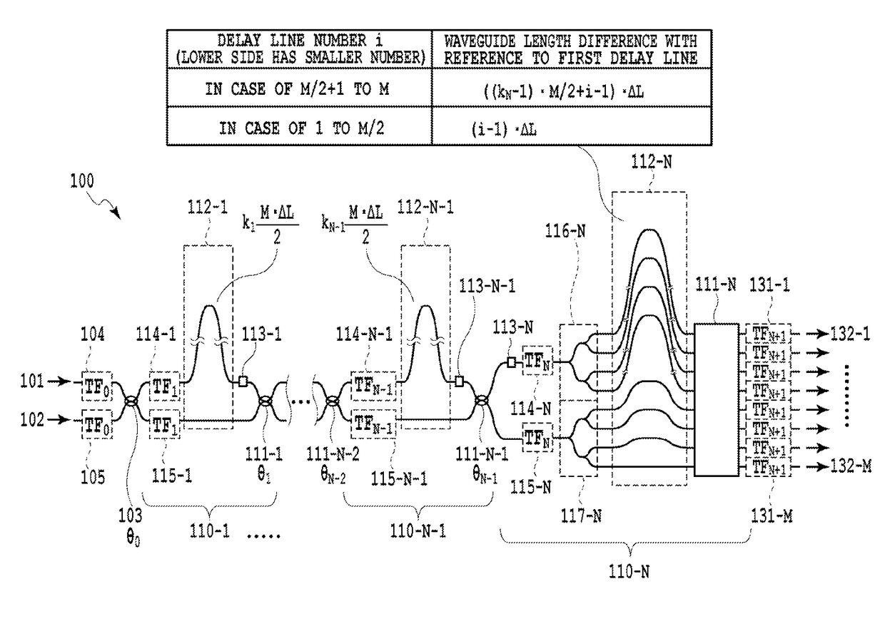
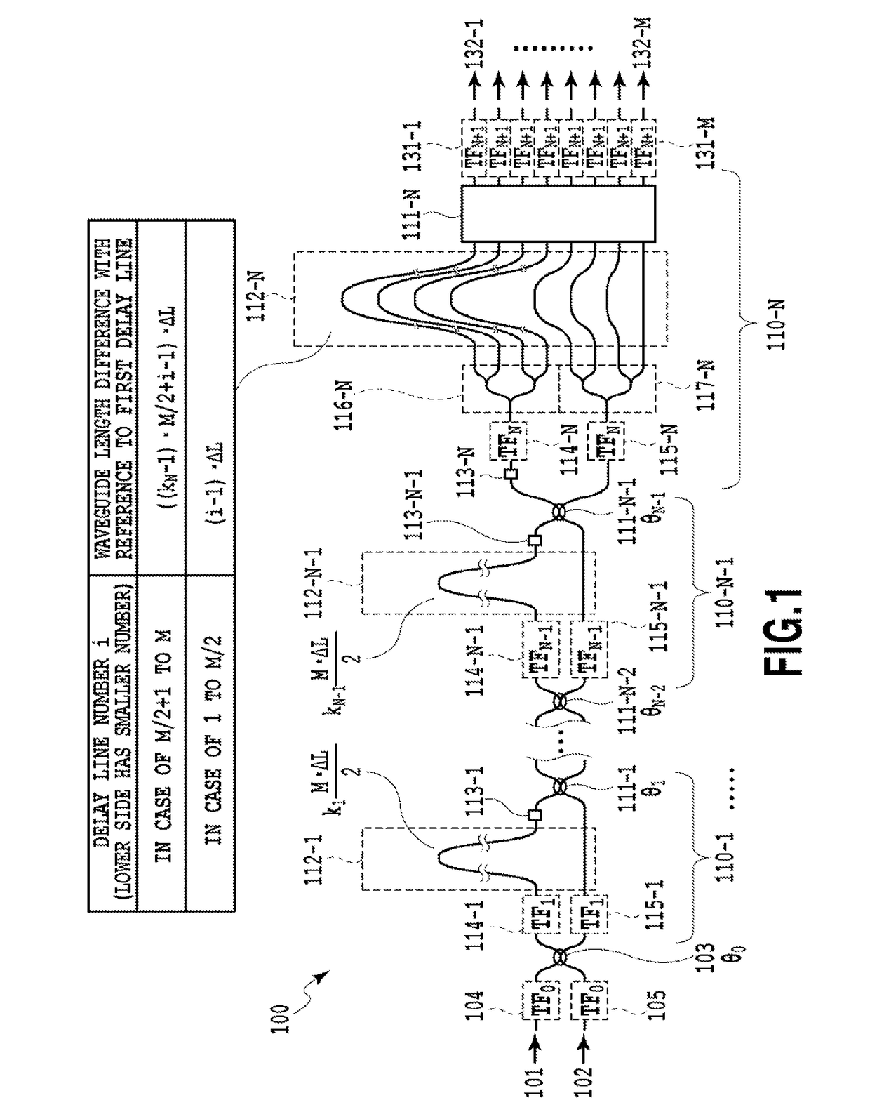
[0142]In the multi-stage interferometer circuit 1500, interferometers 1510-1 to 1510-4 are arranged in series between a 2×2 coupler 1503 that couples the input light coming from input ports 1501 (corresponding to the multiplexing port 101 of FIG. 1), 1502 (corresponding to the multiplexing port 102 of FIG. 1) and output ports 1504-1 to 1504-8 (corresponding to the demultiplexing ports 132-1 to 132-M of FIG. 1). Here, the interferometer 1510-1 of the first stage has a conf...

Example

Second Embodiment

[0152]FIG. 18 is a configuration diagram illustrating a multi-stage interferometer circuit 1800 according to a second embodiment of the present invention. The multi-stage interferometer circuit 1800 of FIG. 18 is also an example when the number of the wavelength-multiplexed / demultiplexed channel, namely, the number of demultiplexing ports is eight (M=8). The number of stages of interferometers is also set to four (N=4), and the design parameters other than the TF are the same as the parameters given in FIG. 3, as in the first embodiment.

[0153]In the multi-stage interferometer circuit 1800, interferometers 1810-1 to 1810-4 are arranged in series between a 2×2 coupler 1803 that couples the input light coming from input ports 1801 (corresponding to the multiplexing port 101 of FIGS. 1) and 1802 (corresponding to the multiplexing port 102 of FIG. 1) and output ports 1804-1 to 1804-8 (corresponding to the demultiplexing ports 132-1 to 132-M of FIG. 1). Here, the interfer...

Example

Third Embodiment

[0161]FIG. 19 illustrates the configuration of a multi-stage interferometer circuit 1900 according to a third embodiment of the present invention. The multi-stage interferometer circuit 1900 of FIG. 15 is also an example when the number of the wavelength-multiplexed / demultiplexed channel, namely, the number of demultiplexing ports, is eight (M=8). The number of stages of interferometers is also set to four (N=4), and the design parameters other than the TF are the same as the parameters given in FIG. 3, as in the first embodiment.

[0162]In the multi-stage interferometer circuit 1900, interferometers 1910-1 to 1910-4 are arranged in series between a 2×2 coupler 1903 that couples the input light coming from input ports 1901 (corresponding to the multiplexing port 101 of FIG. 1), 1902 (corresponding to the multiplexing port 102 of FIG. 1) and output ports 1904-1 to 1904-8 (corresponding to the demultiplexing ports 132-1 to 132-M of FIG. 1). Here, the interferometer 1910-...


PUM


Abstract

A multi-stage interferometer circuit of the present invention includes: a multiplexing port; (N-1) stages of lattice type two-beam interferometers, wherein each stage includes a two-beam delay circuit having a path length difference of an integral multiple of M·Δ L/2, and wherein the two-beam delay circuit of the lattice type two-beam interferometer of the first stage is connected to the multiplexing port; an M-beam interferometer including: two sets of 1×(M/2) optical couplers connected to the first optical coupler of the lattice type two-beam interferometer at the final stage; an M-array delay circuit, each delay circuit of which has a delay length different from each other by ΔL; and M×M optical couplers; and M demultiplexing ports, wherein one or more transversal filters are arranged inside the multi-stage interferometer circuit so that the light guided between the demultiplexing port and the multiplexing ports passes therethrough at least once.

Description

TECHNICAL FIELD[0001]The present invention relates to a multi-stage interferometer circuit having an optical multiplexer / demultiplexer function or an optical filter function, and more specifically relates to a multi-stage interferometer circuit having a waveform-shaping filtering function such as Nyquist shaping.BACKGROUND ART[0002]At present, in the long-distance 100 G transmission in practical use, high-speed transmission of 128 G bps per channel is realized by setting the modulation symbol rate to approximately 32 G baud, by the use of a quadrature phase-shift keying (QPSK modulation) that is one type of multi-value modulation techniques and a polarization multiplexing that is one type of multiplexing techniques. (The transmission rate 28 G bps of the transmission rate 128 G bps is for the bits used for the information and error correction which are required for transmission control and thus the net data transmission rate becomes 100 G bps). In the further higher speed transmissi...

Claims


Application Information

Patent Timeline
IPC IPC(8): H04B10/69G02F1/225G02B6/122
CPCH04B10/69G02B6/122G02F1/225G02B2006/12164G02F2001/212G02B6/2766G02B6/2793G02B6/29355H04J14/0298G02B2006/12038G02B2006/12147G02F1/212
Inventor GOH, TAKASHIITOH, MIKITAKAKIKUCHI, KIYOFUMI
Owner NIPPON TELEGRAPH & TELEPHONE CORP
Why Eureka
Try Eureka