
System and Method for Auto Distilling Liquids at Strictly Defined Conditions Regardless of Composition

a technology of auto-distillation and strict conditions, applied in the direction of hydrocarbon distillation control/regulation, separation process, measurement of optical radiation, etc., can solve the problems of delayed or accelerated observation of ibp, inability to predict the exactness of the prediction, and limited application of prior art to “petroleum-origin fuel”. , to achieve the effect of minimizing human error, improving the prediction of initial heating, and high reproducibility of automated tests

Active Publication Date: 2018-02-08
INSTR SCI DE LABORTOIRE ISL
View PDF0 Cites 9 Cited by
  • Summary
  • Abstract
  • Description
  • Claims
  • Application Information

AI Technical Summary

Benefits of technology

The present invention allows for easy and accurate distillation analysis of unknown liquid samples without the need for skilled operators or prior manual settings. It also improves the prediction of initial heating of the sample and minimizes human error. The invention includes several improvements to the distillation assembly to minimize thermal interference and improve the prediction of initial heating.

Problems solved by technology

However, these predictions may not always be accurate.
In other words, the application of the prior art is limited to “petroleum-origin fuel,” i.e., products produced on the basis of petrol from a first process (e.g., distillation), secondary process, etc.
. . . . As a consequence, when non-petroleum-origin samples are analyzed using the prior art methodology, the observation of the IBP is delayed or accelerated, either case of which may be outside of the selected standard limits.
The distillation assembly of the prior art also contributes to high levels of interference (e.g., internal reflectivity and emissivity) by various components.
These factors contribute to thermal interference and signal distortion, thus, affecting reproducibility and accuracy of the testing.

Method used


Image

  • System and Method for Auto Distilling Liquids at Strictly Defined Conditions Regardless of Composition
  • System and Method for Auto Distilling Liquids at Strictly Defined Conditions Regardless of Composition
  • System and Method for Auto Distilling Liquids at Strictly Defined Conditions Regardless of Composition

Examples


Embodiment Construction

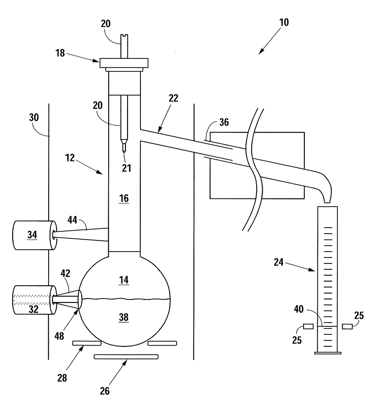
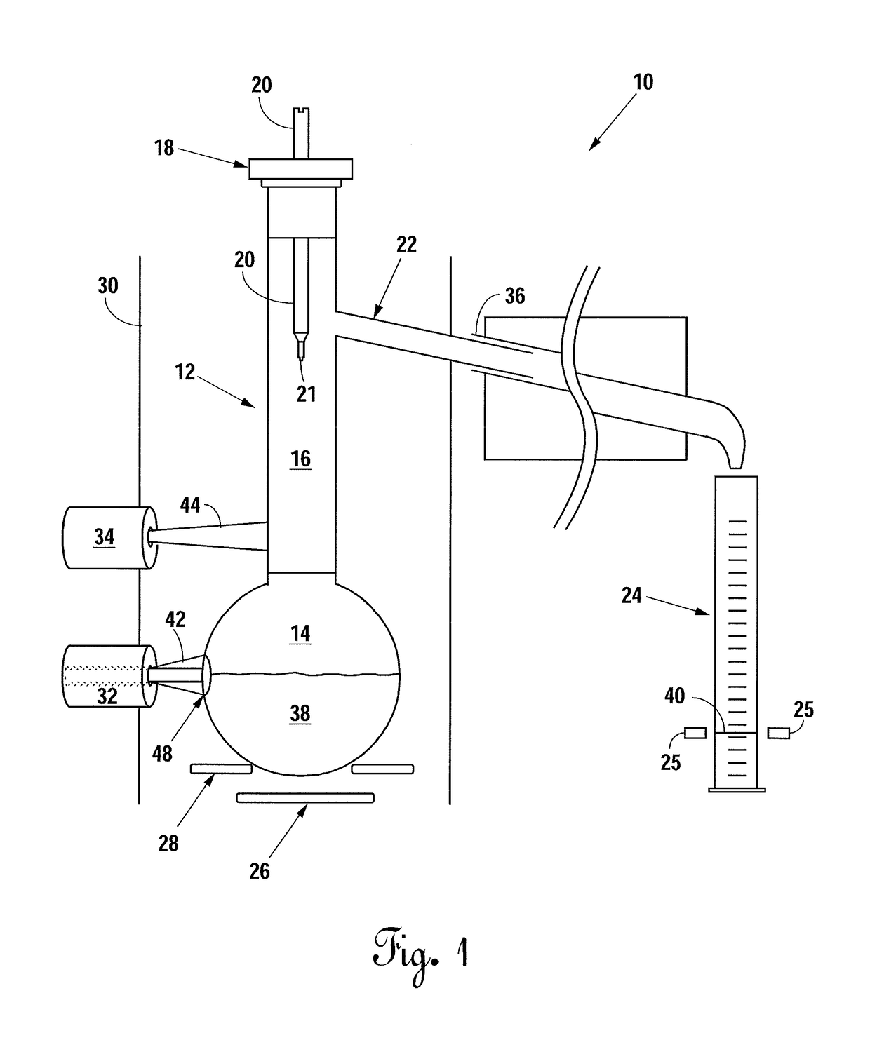
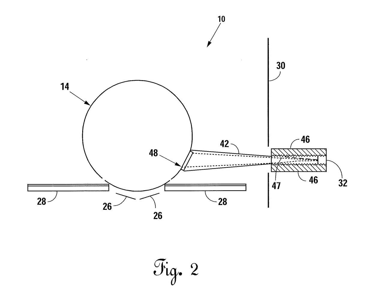
[0034]FIG. 1 depicts the distillation assembly 10 of the present invention. In one embodiment, distillation assembly 10 includes distillation flask 12 with stopper 18, thermometer 20 for measuring vapor temperature, condenser 22, cooling source 36, receiving vessel or collecting flask 24, first and second IR sensors 32 and 34, base plate 28, and heating element 26.

[0035]Distillation flask 12 has a bulb or lower rounded portion 14 and a neck portion 16. Condenser 22 connects to neck portion 16 of distillation flask 12. Stopper 18 seals distillation flask 12 at the top of neck portion 16. Thermometer 20 traverses stopper 18 via an aperture (not shown) in stopper 18 until tip 21 of thermometer 20 is just below where neck portion 16 of distillation flask 12 connects to condenser 22. Cooling source 36 surrounds condenser 22. Collecting flask 24 collects condensate or distillate 40 produced from the distillation process.

[0036]Cooling source 36 (e.g., continuous flow of water or solid-stat...


PUM

PropertyMeasurementUnit
Fractionaaaaaaaaaa
Temperatureaaaaaaaaaa
Compositionaaaaaaaaaa

Abstract

A system and method for distillation of a liquid sample at atmospheric pressure for the improved prediction of the heating necessary before the initial boiling point (IBP) of the sample is detected regardless of sample composition to ensure the IBP is observed within certain time constraints. A plurality of infrared (IR) sensors provides real-time temperature control in addition to a conventional measurement of vapor temperature. One IR-sensor monitors the liquid sample temperature in the distillation flask to obtain a corrected IBP time independent of the sample properties. Another IR-sensor monitors the temperature of the rising vapor column as the vapor rises up the neck of the distillation flask. Alternatively, an IR matrix may monitor the temperature of the rising vapor column. The system and method expand the scope of samples analyzed with improved signal, reproducibility, and test accuracy and still remain within the prescribed limits of a selected standard.

Description

CROSS REFERENCE TO RELATED APPLICATIONS[0001]None.STATEMENT REGARDING FEDERALLY SPONSORED RESEARCH OR DEVELOPMENT[0002]None.BACKGROUND OF THE INVENTION1. Field of the Invention[0003]The present invention relates to distillation. More specifically, the present invention relates to the automatic distillation of liquid samples of unknown compositions at strictly defined conditions.2. Description of the Related Art[0004]Distillation is a common process of separating components with differing volatilities from a liquid mixture by heating and condensing a liquid sample. Generally, distillation is performed using a round bottom flask having a neck portion extending therefrom and a condenser connected to the neck portion of the flask. The other end of the condenser is connected to a receiving vessel or collecting flask. The condenser contains a cooling source, which may generally include a flowing liquid, such as running water, but may also include a solid-state cooling device, such as a Pe...

Claims


Application Information

Patent Timeline
IPC IPC(8): B01D3/42B01D3/02
CPCB01D3/02B01D3/4233B01D3/42B01D5/006C10G7/12G01N25/08G01N25/14G01J5/04G01N33/2829G01N1/4022C10G31/06C10G31/10C10G70/043C10G7/00C10G2400/02C10G2400/04C10G2400/06C10G2400/08G01J5/0806G01J5/0037G01J5/046G01J5/048G01J5/06
Inventor URVANTSAU, VIACHASLAULARCHER, CARENNE
Owner INSTR SCI DE LABORTOIRE ISL
Learn More