Smart contact lenses and smart glasses

a technology of smart glasses and contact lenses, applied in the field of smart contact lenses and smart glasses, can solve the problems of large and heavy use, slow display conversion rate, and high power consumption, and achieve the effects of accurate determination, high stability, and easy and rapid identification of the progression of a patient's diseas

Active Publication Date: 2018-02-08
PHI BIOMED
View PDF4 Cites 21 Cited by
  • Summary
  • Abstract
  • Description
  • Claims
  • Application Information

AI Technical Summary

Benefits of technology

[0018]According to the present invention, a sensor in a contact lens can sense a disease in real time, and therefore the progression of a patient's disease can be easily and rapidly identified. Also, the sensor can be used in a fluid for a long time due to high stability, and more accurately determine whether the disease can be treated or not treated due to high sensitivity.
[0019]Also, technology of sensing a disease marker in the eye such as nitrogen monoxide (NO), VEGF or glucose using a sensor can be applied to various cancer diagnosing systems.
[0020]A drug reservoir inserted into a contact lens can be electrically controlled to release a drug at a desired time, and thus can be applied to treat a variety of eye diseases.
[0021]Aflibercept expressed by a lentivirus, which is inserted into the drug reservoir, is a stable and highly-effective drug for ocular angiogenesis.
[0022]By using a drug reservoir-based drug delivery system capable of being controlled by electrical signals, for example, tetracycline may be released at a desired time, and the system that is turned on or off by the tetracycline can generate a drug in cells. Accordingly, the system can be used in treatment of eye diseases.
[0023]Also, in the present invention, a protein expression-based advanced therapeutic gene introduction method, which has higher biological activity and sustaining power in the body than conventional antibody therapies and prevents apoptosis induced by ADCC and CDC responses can be constructed by introducing hybrid Fc utilizing the characteristics of immunoglobulins present in the body to a therapeutic substance. Therefore, a gene transfer system using an animal trial approximating a clinical trial and a nano system can be produced.

Problems solved by technology

However, such special glasses are too large and heavy to be used for a long time, and thus are inconvenient.
While the Google glass is a pair of multi-functional special glasses having various functions, it consumes high power, has a slow display conversion rate and is very expensive, and therefore it is disadvantageous to be used generally.

Method used


Image

  • Smart contact lenses and smart glasses
  • Smart contact lenses and smart glasses
  • Smart contact lenses and smart glasses

Examples


preparation example 1

Production of Glucose Sensor

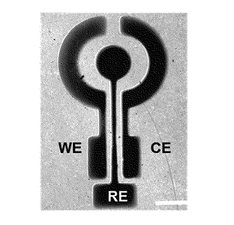
[0093]Three electrodes including a working electrode (WE), a reference electrode (RE) and a counter electrode (CE) were deposited on a polyethylene terephthalate (PET) substrate having a thickness of 25 μm using a shadow mask. A conductive electrode consisting of 20 nm titanium (Ti), 10 nm palladium (Pd) and 200 nm platinum (Pt) was deposited using an e-beam metal evaporator. Additionally, the RE was coated with 200 nm silver (Ag) using Ag / AgCl ink and a shadow mask.

[0094]In addition, glucose oxidase (GOX) was mixed with a poly(3,4-ethylenedioxythiophene)-polystyrene sulfonate (PEDOT-PSS) 1000 solution to have a concentration of 20 mg·mL−1, and then 2 μl of the solution was applied to coat the electrode and hardened in a titanium isopropoxide vapor environment.

[0095]In the present invention, FIG. 1(a) is an image of the glucose sensor produced according to the present invention.

experimental example 1

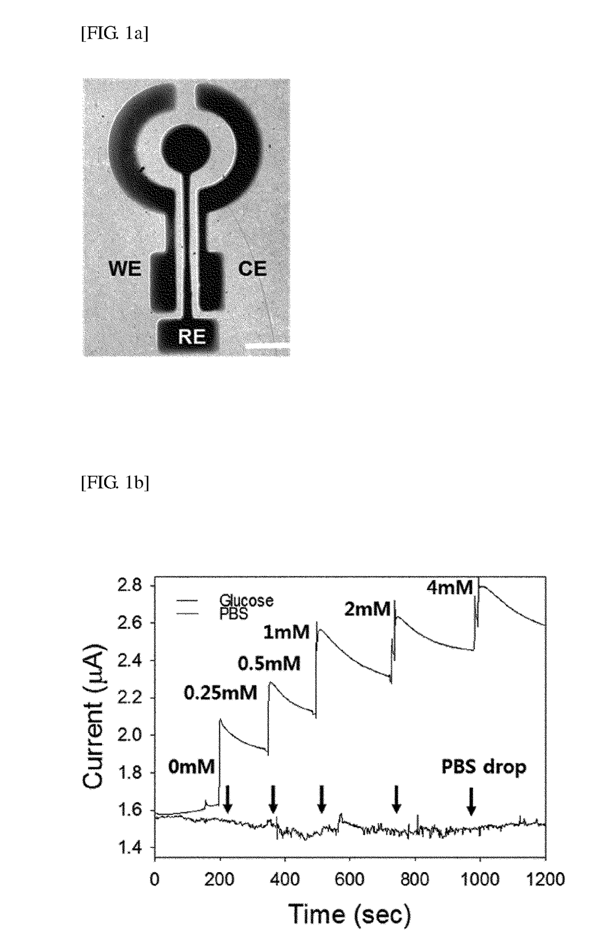
[0096]For the above-described glucose sensor produced in Preparation Example 1, variations in current over time according to the concentration of glucose and variations in current with respect to different materials, other than glucose, were measured.

[0097]To measure the variations in current according to glucose concentration, the glucose sensor was connected with a probe station, 700 mV was supplied, glucose was added in a variety of concentrations of 0, 0.25, 0.5, 1, 2 and 4 mM, and then the current variations were observed.

[0098]The resultant current variations are shown in FIG. 1. FIG. 1(b) is a graph showing the result of measuring the current variations of the glucose sensor over time according to glucose concentration, and FIG. 1(c) is a graph showing the result of measuring the current variations of the glucose sensor with respect to materials, other than glucose.

[0099]As shown in FIG. 1, it can be seen that an increase in current was directly proportional to the glucose co...

preparation example 2

posited Drug Reservoir

[0100]A gold-deposited drug reservoir was produced by the method as follows.

[0101]The drug reservoir was produced by the method illustrated with reference to FIGS. 13(a) to (g).

[0102]First, a glass substrate was prepared (FIG. 13(a)), a hydrogen-containing amorphous silicon layer (a-Si:H) was deposited on the glass substrate, a buffer layer (silicon dioxide, SiO2) was stacked on the amorphous silicon layer, and an electrode pattern was stacked on a partial surface of the buffer layer (FIG. 13(b)). For the electrode pattern, a plurality of positive electrodes may be formed in an array, and a negative electrode may be formed in a window shape. The positive electrodes of the electrode pattern may contain gold, and specifically, Ti / Au / Ti.

[0103]Afterward, a drug well layer (SU-8) was formed on the buffer layer not having the electrode pattern and the electrode pattern and patterned, thereby forming a drug well having an opening. The patterning was performed on the d...


PUM

PropertyMeasurementUnit
weightaaaaaaaaaa
thicknessaaaaaaaaaa
concentrationaaaaaaaaaa

Abstract

The present invention provides a smart contact lens including a sensor capable of non-invasively sensing an eye disease in real time and a drug reservoir, and smart glasses for controlling the smart contact lens.

Description

TECHNICAL FIELD[0001]The present invention relates to a smart contact lens and smart glasses.BACKGROUND ART[0002]Research on smart wearable devices that are compact and light to be equipped on a body and have improved convenience is being very actively conducted. Samsung Electronics, Apple, Google, Nike, Adidas and so forth are representative companies that have researched in earnest to launch innovative products.[0003]Google presented a smart watch after Google Glass 2.0, and recently has attracted new attention with the development of a smart contact lens. Likewise, many global research companies are developing a variety of electronic devices to diagnose and treat human diseases, keeping up with the development of e-health systems. Also, for more convenient treatment of a disease and regular injection and drug administration, a diagnosing system capable of simply controlling a drug delivery system using a smartphone has been developed.[0004]Generally, glasses are used for vision c...

Claims


Application Information

Patent Timeline
Patent Type & Authority Applications(United States)
IPC IPC(8): B29D11/00G02C7/04A61F9/00
CPCB29D11/00096A61F9/0017G02C7/04G02C7/085G02C7/086G02B2027/0178A61B5/14532A61B5/4839A61B5/6821A61K9/0048A61K39/395A61M37/00G01N33/528G01N33/5438G01N33/66G01N2800/164A61K38/1858A61K38/1866A61K48/00G01N33/53G02C11/10
Inventor HAHN, SEI KWANGSUNG, YOUNG CHULMUN, BEOM HOLEE, KEON JAEKEUM, DOHEEKIM, SU JIN
Owner PHI BIOMED
Why Eureka
Try Eureka