Light irradiation substrate

a technology of light irradiation and substrate, which is applied in the field of light irradiation substrate, can solve the problems of treatment light failing on other parts than the affected parts, consuming time and labor, and affecting the normal site, so as to achieve efficient and uniform light irradiation, suppress side effects, and suppress costs

Active Publication Date: 2018-02-15
SHARP KK
View PDF36 Cites 30 Cited by
  • Summary
  • Abstract
  • Description
  • Claims
  • Application Information

AI Technical Summary

Benefits of technology

[0026]One aspect of the present invention may provide a light irradiation substrate that may suppress costs, handle treatments for diseased parts with various sizes, perform substantially uniform light irradiation for an uneven affected part, suppress side effects by light irradiation to a minimum, and realize efficient and uniform light irradiation.

Problems solved by technology

However, the above-described related art has the following problems.
However, in a case of using such a lamp type light source, the treatment light fails on other portions than the affected part because the irradiation area is too large.
Thus, there is a concern about various side effects for a normal site.
Accordingly, some sort of shielding measure for preventing irradiation for the normal site with the treatment light is requested, and a treatment consumes time and labor.
This is not a comfortable experience although the experience is for the treatment.
Further, for example, in a case where the affected part has a curved surface as on an arm or a leg, a lamp type irradiation device may force the patient to keep a very difficult posture depending on a site such as a front side, a back side, or a lateral side.
Thus, a case may occur where it is difficult to uniformly irradiate the whole affected part with the treatment light.
In addition, because a device that uses such a lamp type light source has many accessory devices such as a power source and a cooling device and is large in size, the device requests a large space for installation and is expensive in price.
Meanwhile, in the device that uses laser as the light source, because the irradiation light is spot light with a small irradiation area, scanning by the spot light is requested so that the whole affected part with a large area is irradiated with the treatment light, and the device becomes complicated and expensive.
Further, because the efficiency of delivering light into the optical fibers is comparatively low, a device of a type that performs planar irradiation with the treatment light by using the optical fibers necessarily has low irradiation power and only fits the treatment for a comparatively long time.
Further, the LED is small compared to other light sources and may perform light irradiation for the affected part with a curved surface.

Method used


Image

  • Light irradiation substrate
  • Light irradiation substrate
  • Light irradiation substrate

Examples


first embodiment

[0038]One embodiment of the present invention will be described in the following based on FIGS. 1 to 6. Note that in the following, a description will be made while a surface on which a light-emitting diode (LED) chip is mounted in a light irradiation substrate is defined as a front surface (first surface) and a surface on the opposite side to the surface on which the LED chip is mounted is defined as a back surface (second surface).

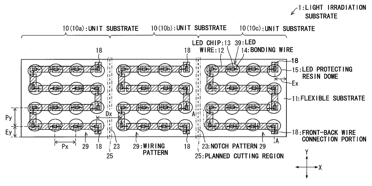
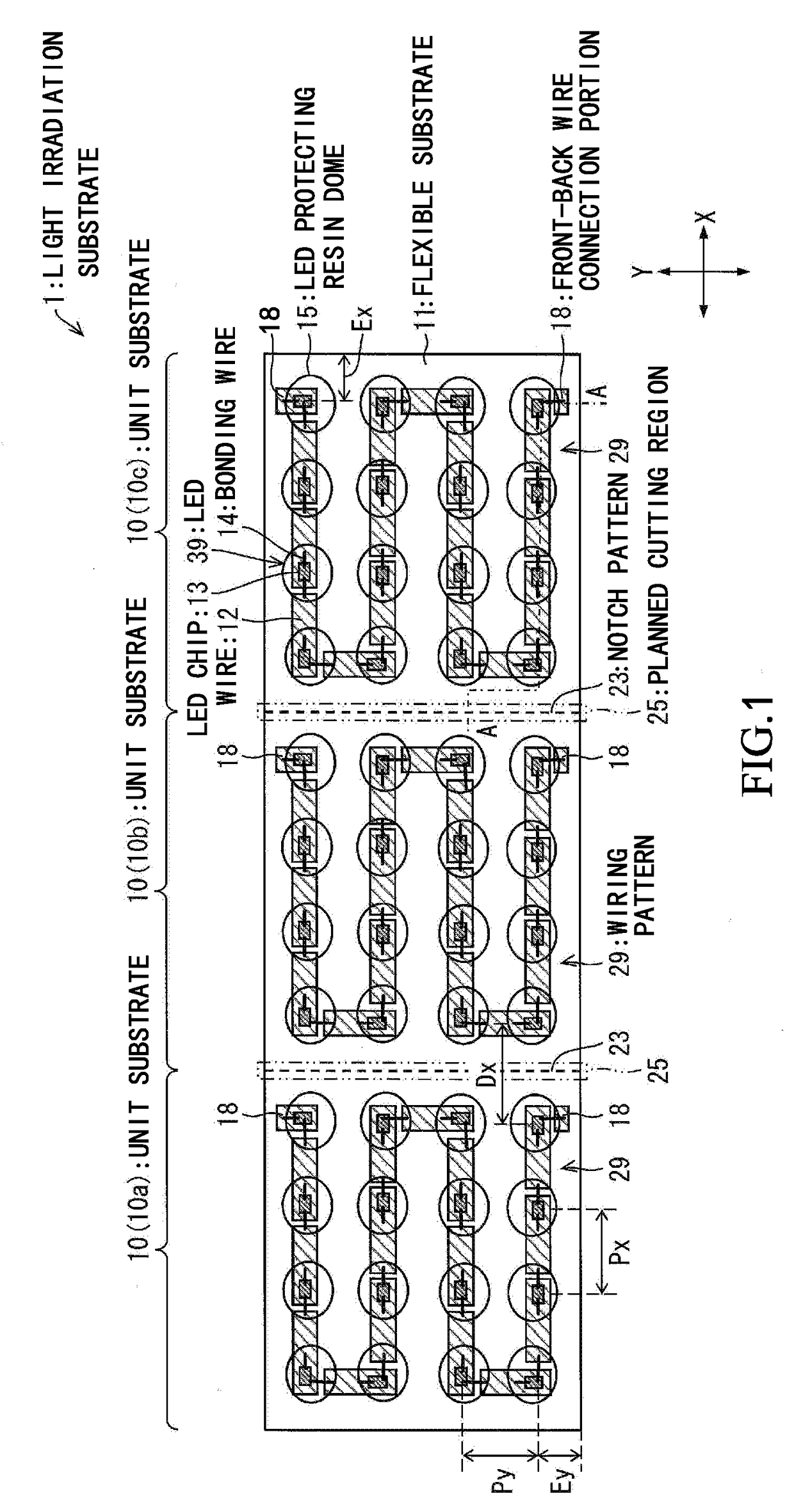
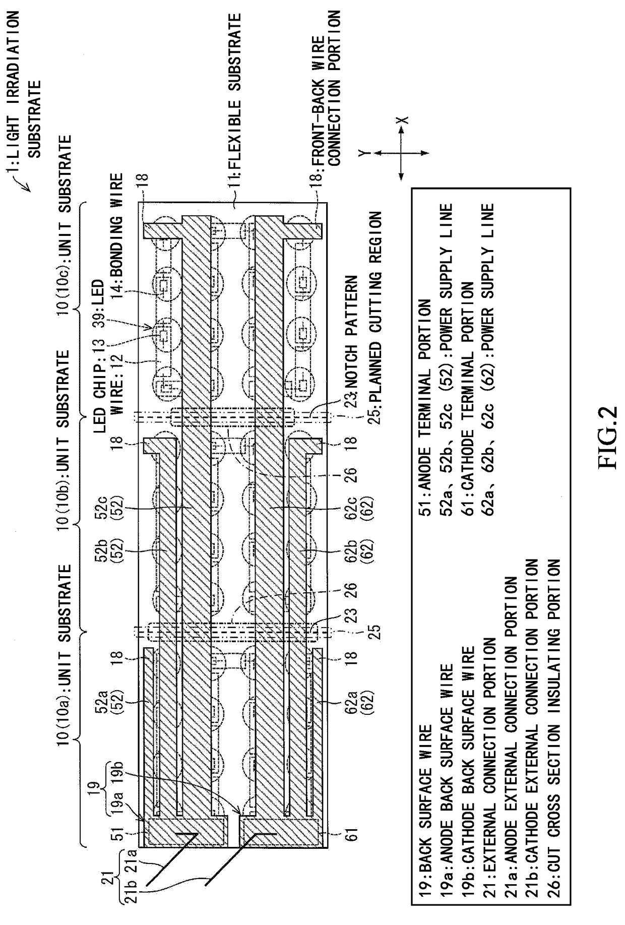
[0039]FIG. 1 is a front surface schematic diagram that illustrates a configuration of a light irradiation substrate 1 according to this embodiment. FIG. 2 is a back surface schematic diagram that illustrates the configuration of the light irradiation substrate 1 according to this embodiment. FIG. 3 is a cross-sectional schematic diagram that illustrates a configuration of a unit substrate according to this embodiment.

[0040]Note that FIG. 3 corresponds to an arrow cross-sectional diagram taken along line A-A of the light irradiation substrate 1 illustrate...

example 1

[0163]In this example, in order to verify the effects of the above light irradiation substrate 1, as illustrated in FIG. 5, an ulcer formed on the back of a pig was caused to be infected with “MRSA”, and the light irradiation substrate 1 of this embodiment was applied to phototherapy that used systemic administration of “ALA” and bluish violet light 34 at a wavelength of 410 nm as the treatment light. A portion of “ALA” is converted to “PpIX” in the body of “MRSA”. “PpIX” is a photosensitized substance and is decomposed by the bluish violet light 34 as described in NPL 1. It is considered that active oxygen that is generated in the decomposition attacks “MRSA” and “MRSA” may thereby be decreased. The phototherapy is expected as a safe treatment method against antibiotic resistant bacteria.

[0164]In this example, two laboratory pigs were prepared, a circular ulcer with a diameter of approximately 20 mm was formed on the back of one pig as sample A, and the ulcer was infected with “MRS...

second embodiment

[0174]Another embodiment of the present invention will be described below based on FIG. 7. Note that in this embodiment, different points from the first embodiment will be described. The same reference characters will be given to configuration elements that have the same functions as the configuration elements described in the first embodiment, and a description thereof will not be made.

[0175]FIG. 7(a) is a front surface schematic diagram of the vicinity of the boundary (planned cutting region 25) between the unit substrates 10 of the light irradiation substrate 1 according to this embodiment. Further, FIGS. 7(b) and 7(c) are cross-sectional schematic diagrams that illustrate the vicinity of the boundary between the unit substrates 10 of the light irradiation substrate 1 illustrated in FIG. 7(a). FIG. 7(b) illustrates a cross section of the light irradiation substrate 1 that is not yet cut, and FIG. 7(c) illustrates a cross section that results from cutting of the light irradiation ...


PUM


Abstract

A light irradiation substrate (1) includes plural unit substrates (10) that have a flexible substrate (11). A portion of the unit substrates (10) have a pair of external connection portions (21). A first surface of the flexible substrate (11) is provided with an LED chip (13) and a wire (12) for each of the unit substrates (10), and a second surface is provided with a back surface wire (19) across the unit substrates (10).

Description

TECHNICAL FIELD[0001]The present invention relates to a light irradiation substrate that is used for phototherapy in which mainly an affected part of human or animal skin is irradiated with light and for hairdressing and beauty treatments.BACKGROUND ART[0002]Phototherapy is used for various purposes such as treatments for diseases such as neonatal jaundice, psoriasis, and acne, pain palliation, and beauty treatments. Green light and blue-white light are used for treatments for neonatal jaundice, ultra-violet light is used for treatments for psoriasis, and blue light, red light, and yellow light are used for treatments for acne. In such a manner, various kinds of light sources are used in accordance with uses.[0003]NPL 1 describes a treatment method for skin ulcer infected with methicillin-resistant Staphylococcus aureus (hereinafter referred to as “MRSA”), which uses near ultra-violet light. This treatment method is a therapeutic method in which an infected part with antibiotic resi...

Claims


Application Information

Patent Timeline
Patent Type & Authority Applications(United States)
IPC IPC(8): A61N5/06
CPCA61N5/0616A61N5/062A61N2005/0652A61N2005/063A61N5/06A61N2005/0632A61N2005/0643A61N2005/0645
Inventor IGUCHI, KATSUJIKAWANISHI, HIDENORIMORI, JUNNAKANISHI, TOHRU
Owner SHARP KK
Why Eureka
Try Eureka