

High-Purity Dispense System
a technology of dispense system and film, applied in the field of semiconductor fabrication, can solve the problems of reducing the efficiency of dispense system, and reducing so as to minimize the exposure of process fluid to gas and atmosphere, and reduce the defectivity of deposited films
- Summary
- Abstract
- Description
- Claims
- Application Information
AI Technical Summary
Benefits of technology
Problems solved by technology
Method used
Image

Examples
Embodiment Construction
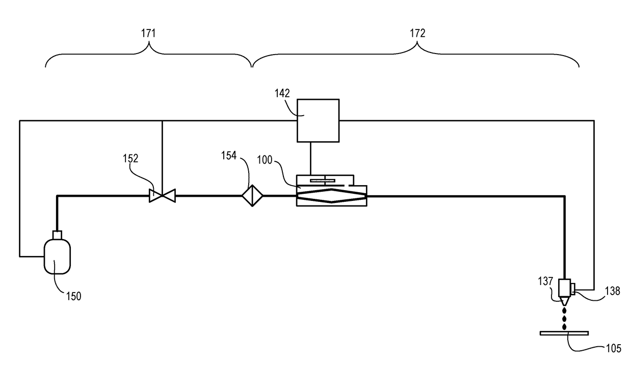
[0027]Techniques herein can be embodied as a bladder-based dispense system using an elongate bladder. This dispense system compensates for filter-lag, which often accompanies fluid filtering for microfabrication. This dispense system also provides a high-purity and high precision dispense unit. This dispense solution herein further reduces chances for defect creation. Conventional fluid delivery systems typically have a “dead leg” hanging off a fluid line. This dead leg can be a branch off the fluid line such as for a pressure measuring device or reservoir. Conventional fluid delivery systems can have other discontinuities that result in a significant chance of creating defects in the fluid, including various valves. Fluid connectors are designed to reduce imperfections on fluid conduit walls (inside walls). Any rough connectors or bends can cause places where fluid can recirculate, slow down, or otherwise get stopped which can cause coagulation. Thus, having a piston, baffle, or si...
PUM
 Abstract
Description
Claims
Application Information