Multiple-keyed flywheel and engine crankshaft

a multi-keyed, flywheel technology, applied in the direction of crankshafts, machines/engines, automatic control, etc., can solve the problems of loose fitting, inability to draw to scale, and inability to facilitate different relative arrangements of engines in a single apparatus

Active Publication Date: 2018-03-15
KOHLER CO
View PDF8 Cites 2 Cited by
  • Summary
  • Abstract
  • Description
  • Claims
  • Application Information

AI Technical Summary

Problems solved by technology

However, engine designs do not facilitate different relative arrangements in a single apparatus.
Modifying the timing of the firing of the spark plug may be due to fuel not completely burning at the exact time the spark plug fires.
Likewise, the small key and keyw...

Method used


Image

  • Multiple-keyed flywheel and engine crankshaft
  • Multiple-keyed flywheel and engine crankshaft
  • Multiple-keyed flywheel and engine crankshaft

Examples


Embodiment Construction

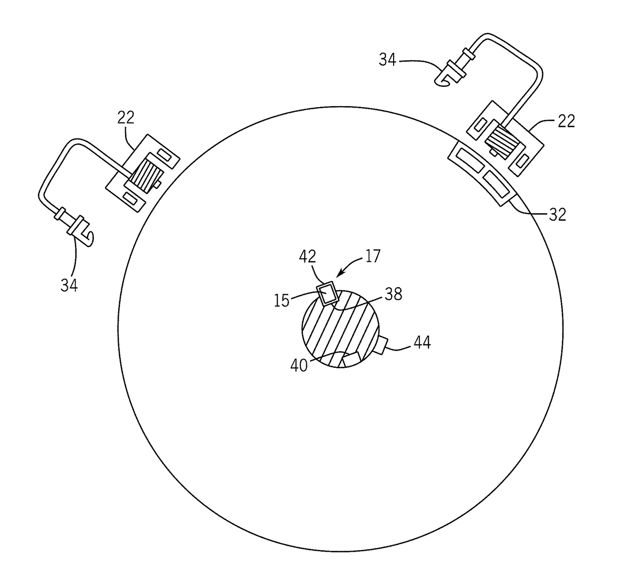
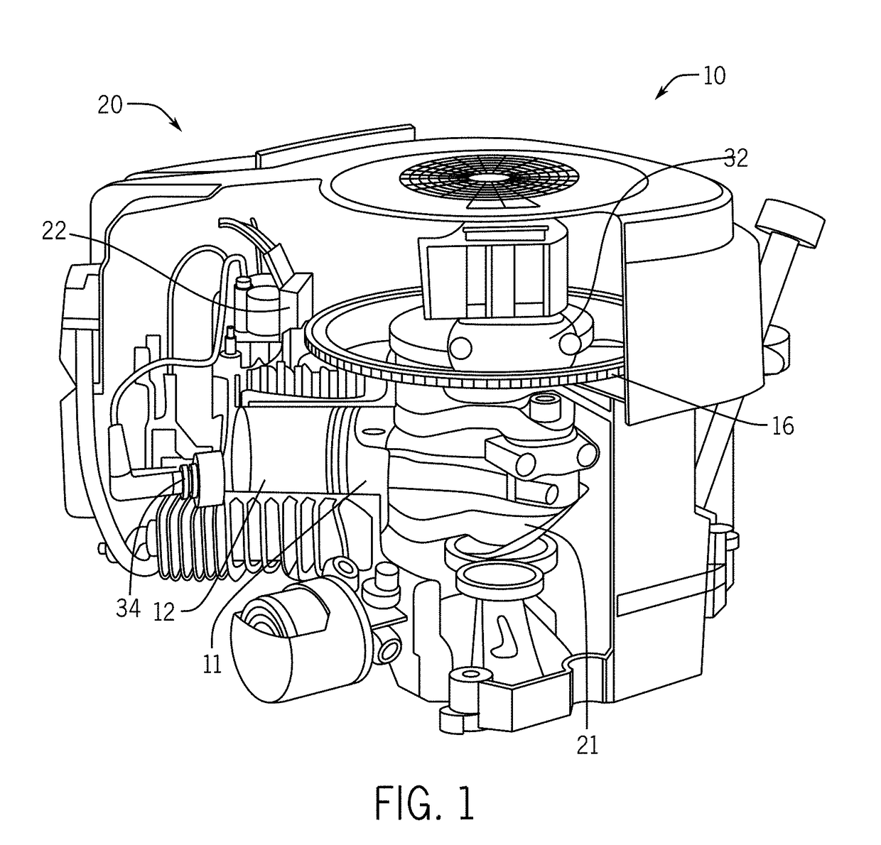
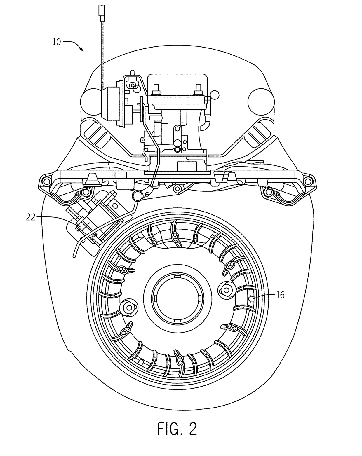
[0023]A small engine often includes a flywheel disposed on a crankshaft. The rotating flywheel includes a magnet that passes an ignition module fixed to the engine to control engine spark within a cylinder during the compression stroke of the piston. Ignition timing varies for each engine and fuel type. Engine ignition timing may be based on the degrees before top dead center (“TDC”) of the piston within the cylinder where ignition of the spark plug produces the most power and efficiency.

[0024]Ignition timing may vary for each engine and fuel type. The size of the engine cylinder and piston may affect ignition timing within an engine. Likewise, the type of fuel in combination with the engine (i.e. gaseous or liquid) may also affect the ignition timing of an engine. Each fuel type has an ideal burn rate and compression ratio that affects the ignition timing of an engine. In some instances, the same engine may operate with different selected fuel types (i.e. gasoline, natural gas, pro...


PUM


Abstract

A multiple-keyed crankshaft and flywheel provides for different ignition timing options for an internal combustion engine. The crankshaft of the engine includes multiple keyways set at designated angular displacements of the crankshaft that correspond with keyways on a flywheel for providing different timing options for the engine. The flywheel may be mounted to the crankshaft by aligning one of the keyways of the flywheel to one of the keyways of the crankshaft related to a particular ignition timing selection.

Description

TECHNICAL FIELD[0001]This disclosure relates in general to a multiple-keyed flywheel and / or engine crankshaft for an internal combustion engine, or more particularly, multiple keyways in a flywheel and multiple keyways within a crankshaft for optional ignition timing of an internal combustion engine.BACKGROUND[0002]Small internal combustion engines are used in a variety of devices including, but not limited to: generators, chainsaws, lawn mowers, weed trimmers, all-terrain vehicles, wood splitters, pressure washers, garden tillers, snow blowers, or other devices. A small engine often includes a flywheel disposed on a crankshaft. The flywheel stores rotational energy from the crankshaft or prime mover of an engine. Through momentum and inertia, from one or more of the series of strokes energy, is received from the crankshaft and then delivered to the crankshaft or prime mover in another one or more of the series of strokes. Various engine models may include different relative arrange...

Claims


Application Information

Patent Timeline
IPC IPC(8): F02P1/00F16C3/06F16F15/315
CPCF02P1/005F16F15/3153F16C3/06F02P5/145F16F15/24F16F15/30F16C2360/00F16C3/10F02P1/02
Inventor KLECZEWSKI, MICHAELWEBSTER, JAMES
Owner KOHLER CO
Why Eureka
Try Eureka