Radar System

a radar system and signal processing technology, applied in the field of radar signal processing, can solve the problems of target detection problem boiling down, detection problem further compounded, and difficult radar signal processing in practice, and achieve the effect of eliminating clutter signal components

Active Publication Date: 2018-03-15
SRC INC
View PDF5 Cites 16 Cited by
  • Summary
  • Abstract
  • Description
  • Claims
  • Application Information

AI Technical Summary

Benefits of technology

[0037]In another aspect, the present invention is directed to a method for use in a radar system, the method comprising: providing a plurality of digital signals corresponding to incident RF signals reflected from an operating environment, the plurality of digital signals including clutter signal components; providing a two-dimensional image of the operating environment based on the plurality of digital signals, the two-dimensional image including a plurality of pixel elements representative of the operating environment; converting the two-dimensional image into a clutter classification map

Problems solved by technology

While the above stated process sounds relatively straightforward in theory, radar signal processing can be challenging in practice.
Moreover, military commanders must use their assets smartly and efficiently since resources are limited.
The detection problem is further compounded by the presence of “white noise” or random Gaussian noise that is generated by the radar receiver circuitry itself.
Thus, the target detection problem boils down to the ability to distinguish an RF target return signal from clutter and noise signals.
This problem is exacerbated when the target has a small radar cross section (RCS), which is the measure of an object's ability to reflect radar signals back towards the radar receiver, and/or if the target is relatively slow moving.
One drawback to this approach relates to the fact that airborne or spaceborne platforms are typically in motion when the radar is operating.
One drawback to STAP relates to the problems associated with selecting appropriate training data.
However, in a nonhomogeneous terrain environment this assumption may not be valid.
As FIG. 1 illustrates, a target may be surrounded

Method used


Image

  • Radar System
  • Radar System
  • Radar System

Examples


Embodiment Construction

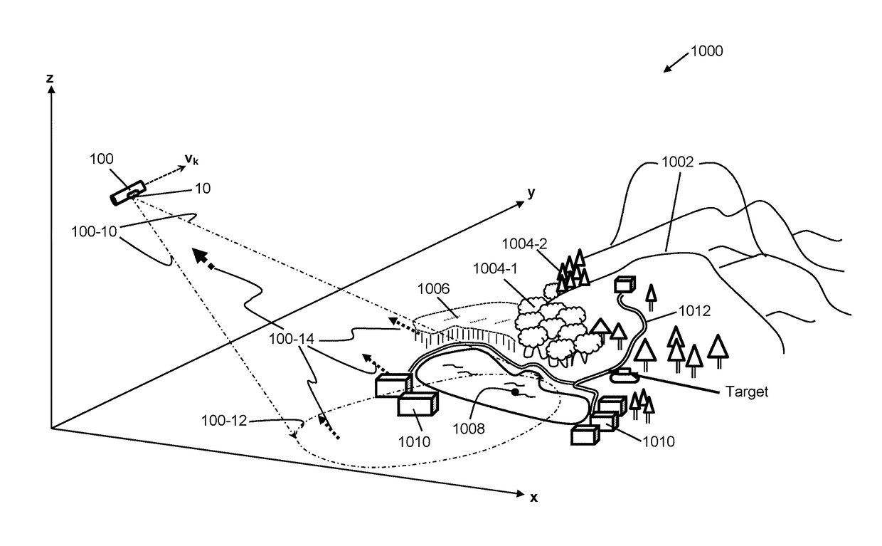
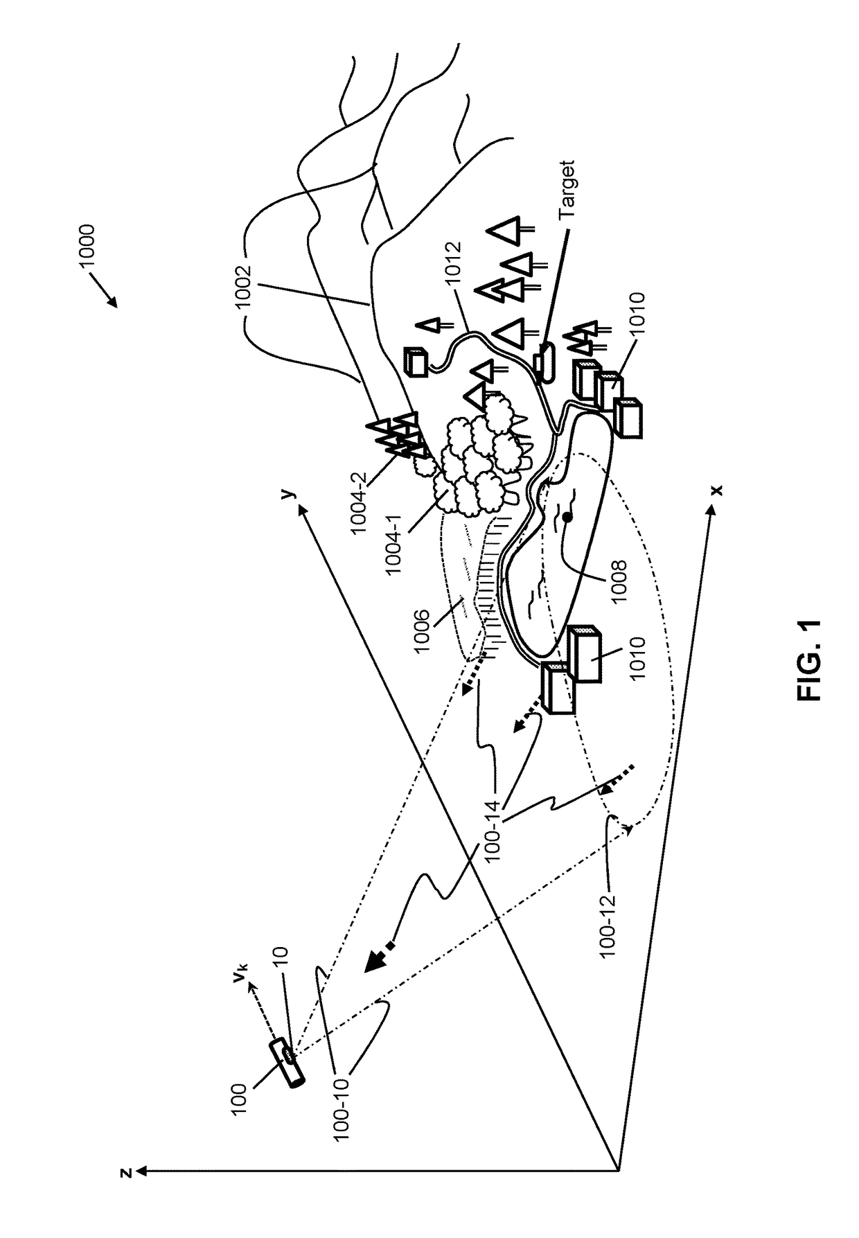
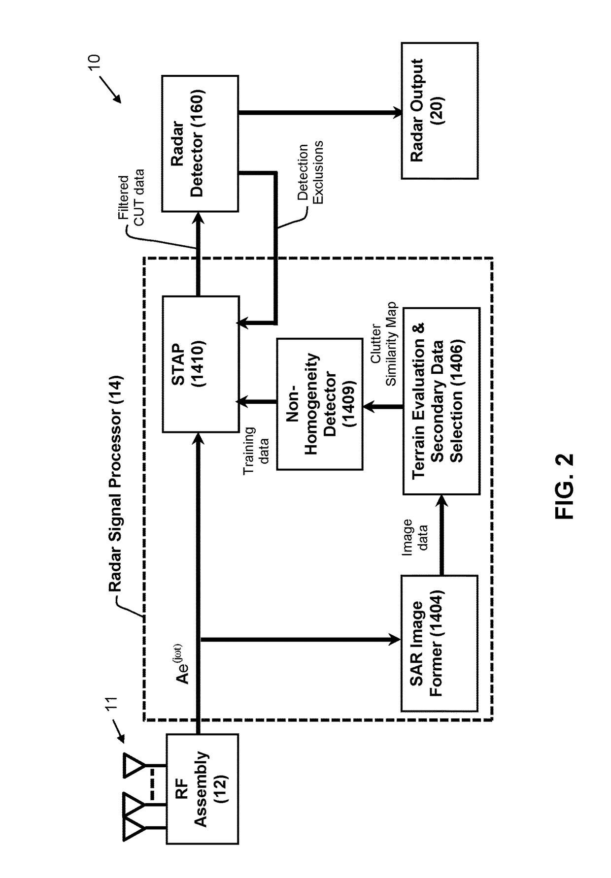
[0069]Reference will now be made in detail to the present exemplary embodiments of the invention, examples of which are illustrated in the accompanying drawings. Wherever possible, the same reference numbers will be used throughout the drawings to refer to the same or like parts. An exemplary embodiment of the radar system of the present invention is shown in FIG. 2, and is designated generally throughout by reference numeral 10.

[0070]As embodied herein, and depicted in FIG. 2, a high level block diagram of the system 10 in accordance with an embodiment of the present invention is disclosed. The system 10 includes an antenna array 11 coupled to an RF assembly 12. In any space-time adaptive processing radar, multiple antenna elements / channels are required. Those skilled in the art will appreciate that the antenna array 11 may include a linear 1×N array, N being an integer value greater than two (2), or a two dimensional L×N array, wherein L and N are integer values greater than two (...


PUM


Abstract

A radar system includes an image forming circuit that provides a two-dimensional image of an operating environment. The image includes pixel elements representative of the operating environment. The system includes at least one filter configured to convert the two-dimensional image into a clutter classification map of clutter regions. A predetermined number of clutter regions are selected as training cells for a predetermined cell-under-test (CUT). A space-time adaptive processor (STAP) is configured to derive a weighted filter from training cell data. The STAP applies the weighted filter to a digital return signal associated with the predetermined CUT to provide a STAP-filtered digital return signal having the clutter signal components substantially eliminated therefrom.

Description

BACKGROUND OF THE INVENTION1. Field of the Invention[0001]The present invention relates generally to radar signal processing, and particularly to radar signal processing that employs agile data selection for space-time adaptive processing.2. Technical Background[0002]The word “radar” is actually an acronym that stands for “RAdio Detection And Ranging.” A radar system is one that employs radio frequency (RF) signals to detect (or image) a variety of objects such as aircraft, ships, spacecraft, guided missiles, motor vehicles, weather formations, and terrain. When detecting an object, the radar system can be configured to determine the object's range (distance), bearing (angle), and / or velocity. Briefly stated, when the radar transmits an RF signal that impinges an object, a return signal is reflected back toward the radar receiver. The return signal is detected if it is stronger than the noise signals that may be present in the receiver. A target's bearing corresponds to the directio...

Claims


Application Information

Patent Timeline
IPC IPC(8): G01S13/524G01S13/90
CPCG01S13/5244G01S13/90G01S13/08G01S13/42G01S13/867
Inventor CAPRARO, CHRISTOPHER THOMASPILTCH, EVA BETHSTEEGER, JASON MICHAEL
Owner SRC INC
Why Eureka
Try Eureka