Eureka AIR delivers breakthrough ideas for toughest innovation challenges, trusted by R&D personnel around the world.

Method for promoting electrical conduction between metallic components and composite materials

Active Publication Date: 2018-03-22
THE BOEING CO
View PDF0 Cites 2 Cited by
  • Summary
  • Abstract
  • Description
  • Claims
  • Application Information

AI Technical Summary

Benefits of technology

The present invention is a method, apparatus and article of manufacture for promoting electrical conduction between metallic components and composite materials. This is achieved by coating the composite body with an adhering layer comprising a conductive material and connecting the metallic component to the conductive material in the adhering layer. The adhering layer is made of an electrically conductive ink or electrically conductive paint that includes copper or silver particles and low temperature sintering agents. The adhering layer can be applied to the composite body using various methods such as screen-printing or plating. The temperature of the adhering layer during curing does not affect the composite body and can be performed using baking, flash radiant heating, or laser heating. This invention is useful in various fields such as aerospace, automotive, and electronics.

Problems solved by technology

However, sleeved fasteners are very expensive to purchase and use, and involve many inspections during installation and repair.
The extensive use of sealant not only adds cost and factory flow time, but is proving to be unpopular with customers.
However, clearance-fit fasteners normally provide poor electrical contact to drilled holes in composite materials, which results in arcs and sparks.
However, past attempts to use particle-laden paints have been unsuccessful, due to their modest conductivity and difficulties in their application.
However, liquid metals tend to form brittle intermetallic compounds with titanium and other structural metals, which could severely degrade a fastener's mechanical properties.

Method used


Image

  • Method for promoting electrical conduction between metallic components and composite materials
  • Method for promoting electrical conduction between metallic components and composite materials
  • Method for promoting electrical conduction between metallic components and composite materials

Examples


Embodiment Construction

[0026]In the following description of the preferred embodiment, reference is made to the accompanying drawings which form a part hereof, and in which is shown by way of illustration a specific embodiment in which the invention may be practiced. It is to be understood that other embodiments may be utilized and structural changes may be made without departing from the scope of the present invention.

[0027]Structure Description

[0028]In one embodiment, electrical conduction is promoted between metallic components and composite materials. The metallic components and composite materials are used in aircraft and aerospace vehicles, structures, and applications, and the electrical conduction thus promoted improves the function of lightning protection systems, electromagnetic effects management systems, or grounding systems.

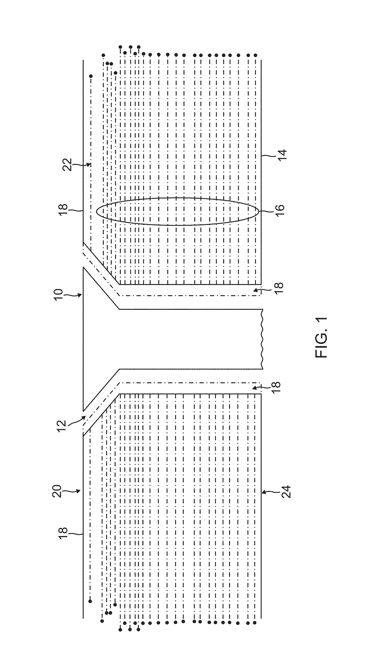
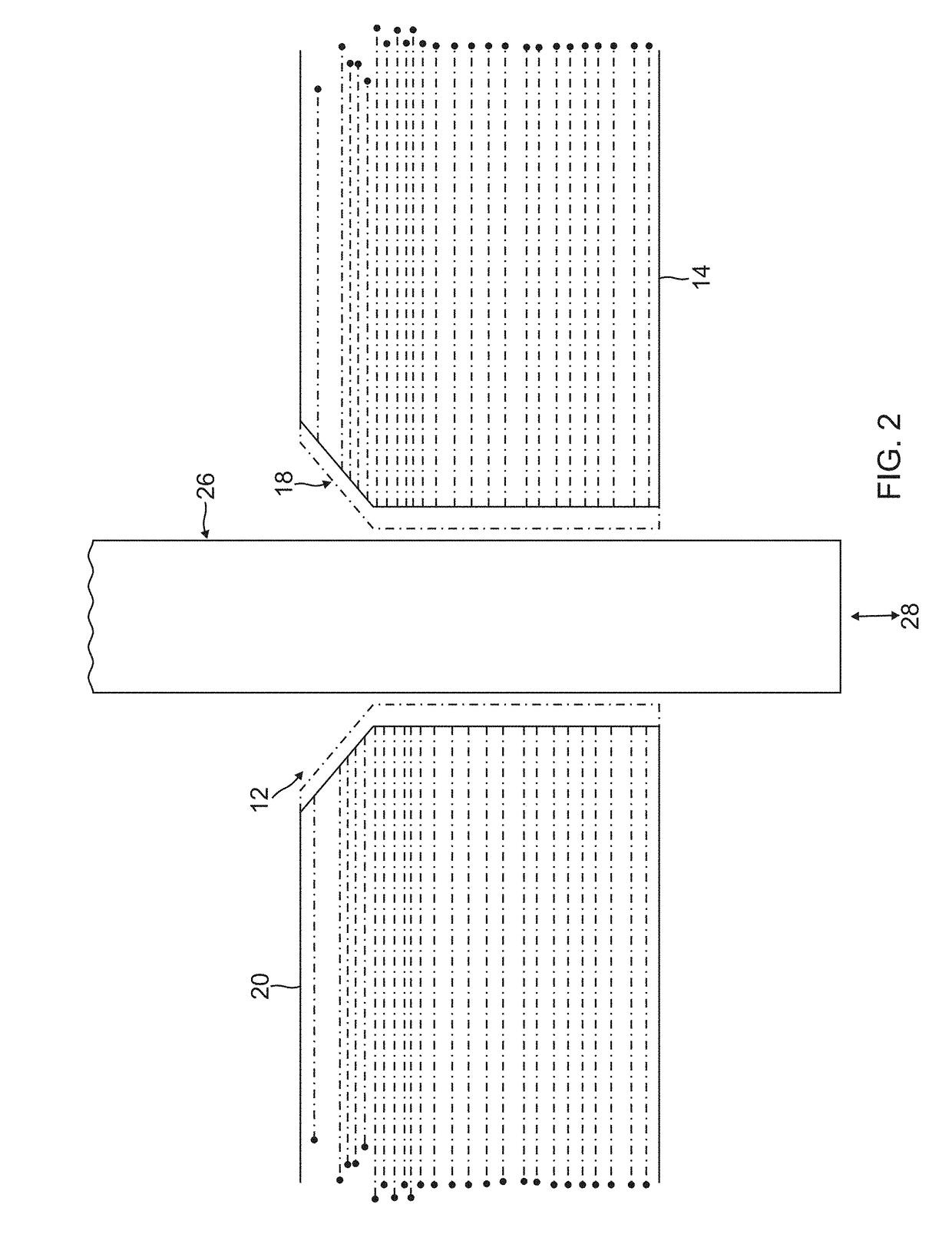
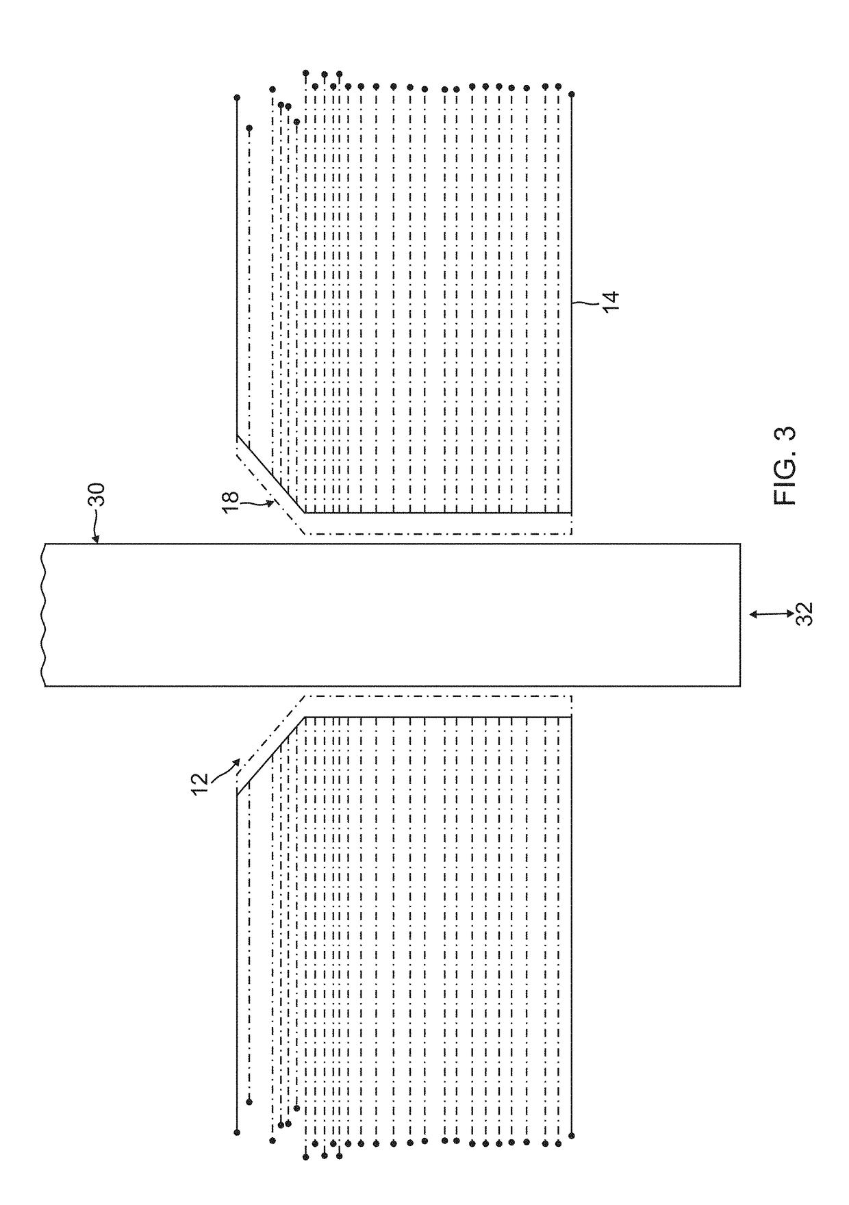
[0029]FIG. 1 is a cross-sectional view illustrating a structure according to one embodiment, which includes a metallic component 10 inserted into a hole 12 drilled into a ...


PUM

PropertyMeasurementUnit
Temperatureaaaaaaaaaa

Abstract

A method for promoting electrical conduction between metallic components and composite materials. A composite body is coated with an adhering layer comprising a conductive material, and a metallic component is electrically connected to the conductive material of the adhering layer, when the metallic component is coupled to the composite body. The adhering layer is deposited inside a hole in the composite body, and / or along an edge of the hole, and / or on at least a portion of a surface of the composite body. The composite body is a structure of an aircraft or other vehicle comprised of composite materials formed from carbon fiber-reinforced polymers (CFRPs), the metallic component is a fastener or is positioned at an interface between the fastener and the composite body, and the electrical connection is made as part of a lightning protection system, an electromagnetic effects (EME) management system, or grounding system.

Description

CROSS REFERENCE TO RELATED APPLICATION[0001]This application claims the benefit under 35 U.S.C Section 119(e) of the following co-pending and commonly-assigned application:[0002]U.S. Utility application Ser. No. ______, filed on same date herewith, by Carl R. McIver, Dejan Nikic and Arthur C. Day, entitled “METHOD FOR PLACING ELECTRICAL CONDUCTORS INTERIOR TO A COMPOSITE STRUCTURE PRIOR TO CURING,” attorneys' docket number 16-1526-US-NP;[0003]which application is incorporated by reference herein.BACKGROUND INFORMATION1. Field[0004]The invention is related generally to a method for promoting electrical conduction between metallic components and composite materials.2. Background[0005]Lightning protection and electromagnetic effects (EME) management systems are used in aircraft to prevent arcing or sparking in or near fuel tanks, and electrical damage to other components of the aircraft. Such systems not only dissipate lightning strikes, they provide for electrical shielding, grounding...

Claims


Application Information

Patent Timeline
IPC IPC(8): B32B7/14C09D11/52B32B27/20
CPCB32B7/14C09D11/52B32B27/20B32B2255/10B32B2307/202B32B2605/18B32B2262/106B64D37/32B64D45/02C09D5/24
Inventor DAY, ARTHUR C.MCIVER, CARL ROYNIKIC, DEJAN
Owner THE BOEING CO
Why Eureka
Eureka Blog
Learn More