Bonding objects together

a technology of objects and bonding elements, applied in the field of mechanical engineering and construction, can solve the problems of new challenges in bonding elements of these materials, substantial galvanic corrosion, and special difficulties, and achieve the effects of strong heating, high energy absorption, and potentially very fast processing

a technology of objects and bonding elements, applied in the field of mechanical engineering and construction, can solve the problems of new challenges in bonding elements of these materials, substantial galvanic corrosion, and special difficulties, and achieve the effects of strong heating, high energy absorption, and potentially very fast processing

US20180094660A1Active Publication Date: 2018-04-05WOODWELDING

Image

  • Bonding objects together
  • Bonding objects together
  • Bonding objects together

Examples


Embodiment Construction

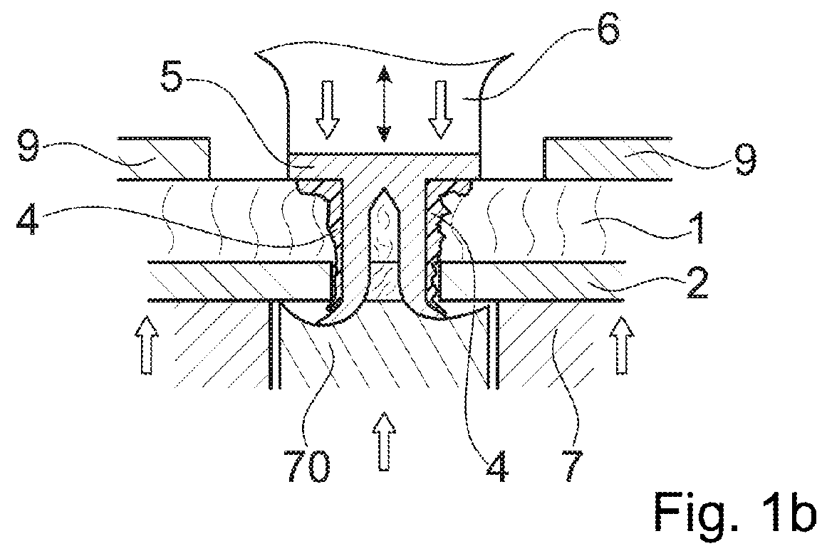
[0138]FIG. 1a depicts a basic set-up of embodiments of the invention. The first object 1 is a board or sheet, for example of a fiber composite material (fiber reinforced polymer material) such as a Carbon fiber-reinforced polymer (CFRP) or a Fiberglass. It has an essentially flat sheet portion with two, for example, essentially parallel broad surfaces. The broad surface that in the figures is the upper surface is herein termed “proximal” surface and the opposing surface is the “distal” surface.

[0139]The second object 2 is made of a metal. It also has a sheet portion with the proximal broad surface of the sheet portion lying against the distal broad surface of the first object's sheet portion.

[0140]In a variant shown in FIG. 2, between the first and second objects a further layer, such as an adhesive and / or separating insulating layer 8, may be present. Such additional layer may, for example, be formed of a thermoplastic material, or it may be formed of a resin, for example a not cur...


PUM

PropertyMeasurementUnit
Temperatureaaaaaaaaaa
Thicknessaaaaaaaaaa
Forceaaaaaaaaaa

Abstract

A method of bonding a connector to a first object includes providing the first object and the connector, the connector extending between a proximal end and a distal end and has a connector body that forms a distally facing punching edge. At least one of the connector and of the first object includes a thermoplastic material in a solid state. The method further includes driving the connector into the first object and coupling mechanical vibration into the connector until the connector extends through a portion of the first object from a proximal side to a distal side thereof and material of the first object is punched out by the connector body, and until at least a flow portion of the thermoplastic material becomes flowable and flows relative to the first object and the connector body while the connector body remains solid. Thereafter, the thermoplastic material is allowed to re-solidify.

Description

BACKGROUND OF THE INVENTIONField of the Invention[0001]The invention is in the fields of mechanical engineering and construction, especially mechanical construction, for example automotive engineering, aircraft construction, shipbuilding, machine construction, toy construction etc.Description of Related Art[0002]In the automotive, aviation and other industries, there has been a tendency to move away from steel constructions and to use lightweight material such as aluminium or magnesium metal sheets or die-cast parts, or carbon fiber reinforced polymers instead.[0003]The new materials cause new challenges in bonding elements of these materials—especially of bonding flattish objects (such as panels or boards) together or bonding a flattish object and an other object together, such as bonding a flattish object to an other object, or bonding a connector to a flattish object.[0004]Difficulties especially arise if objects of different materials are to be connected, such as two materials o...

Claims


Application Information

Patent Timeline
05 Apr 2018
Publication
US20180094660A1
IPC
F16B5/04; F16B19/08; B29C65/56; B29C65/64; B29C65/00
CPC
F16B5/04; F16B19/086; B29C65/562; B29C65/645; B29C66/742; B29C66/721; F16B11/006; B21J15/025
Inventors
MAYER, JORG; LEHMANN, MARIO