Wave power station
a power station and wave technology, applied in the direction of engine components, engine fuction, sea energy generation, etc., can solve the problems of high investment cost, wave power station complex, wear and tear or damage, etc., and achieve the effect of easy movement or scrapping
- Summary
- Abstract
- Description
- Claims
- Application Information
AI Technical Summary
Benefits of technology
Problems solved by technology
Method used
Image
Examples
first embodiment
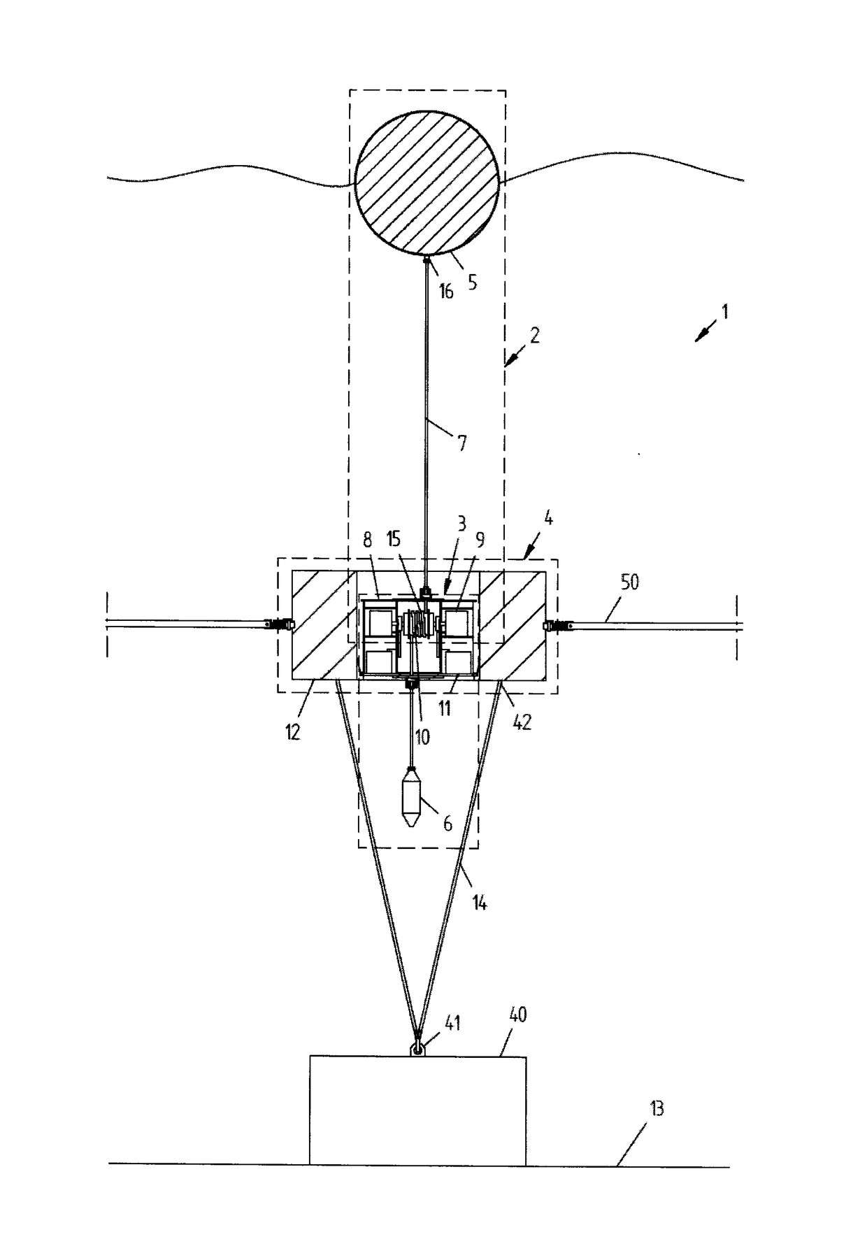
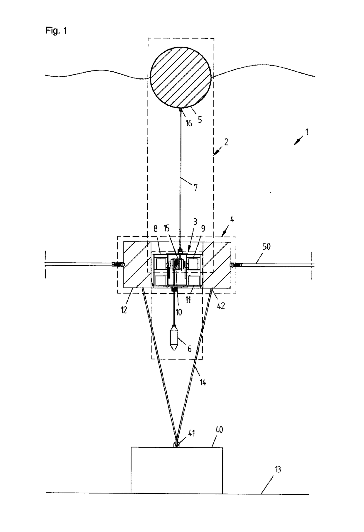
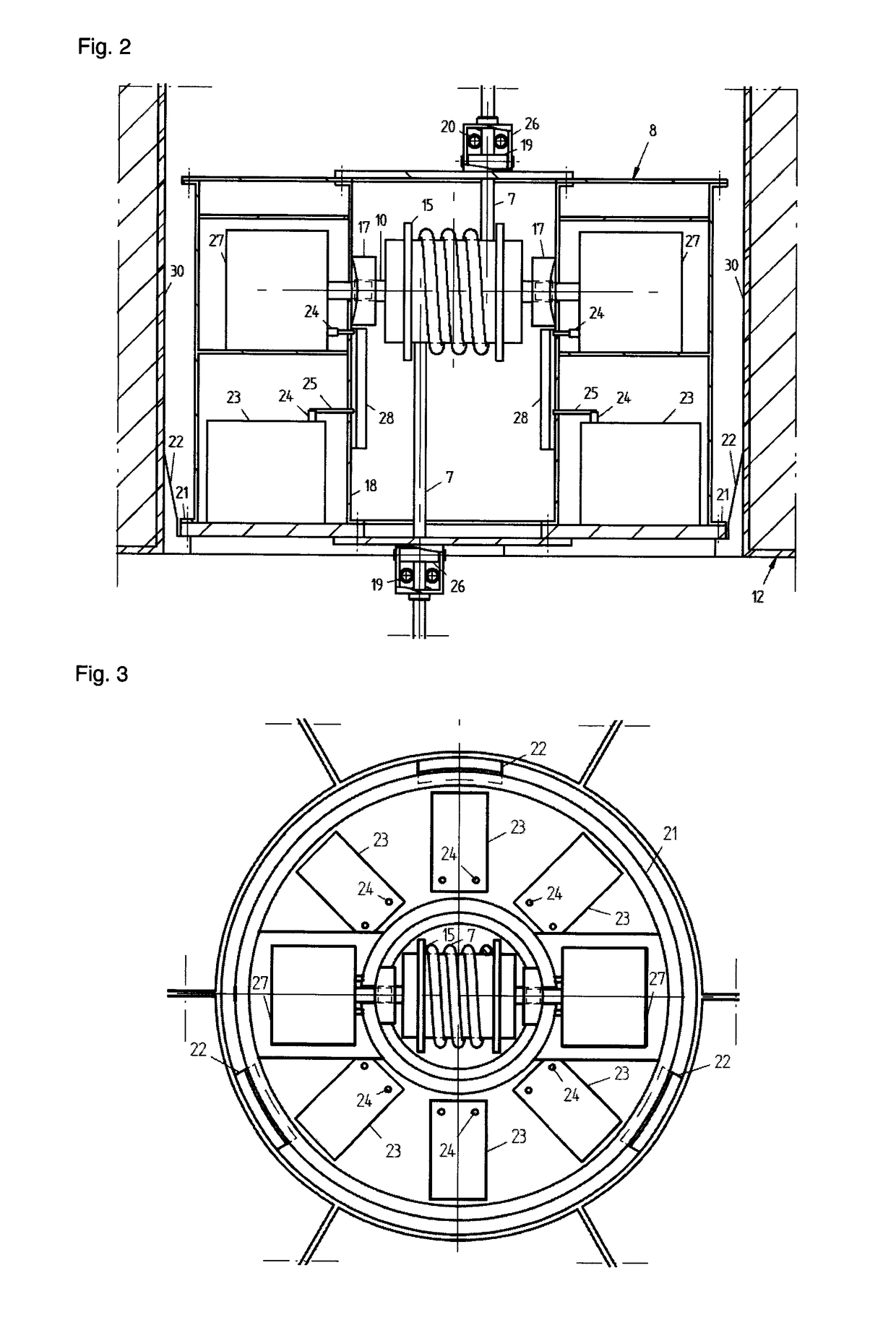
[0054]The power generating unit 3 comprises at least one power generation unit 9, which in the wave power station 1, FIGS. 2 and 3, is constituted by two opposite-acting electric generators 27, the rotor shafts of which are connected to a drive shaft 10, which, via the drive wheel 15 and the movements of the drive line 7, drives the two opposite-acting electric generators 27.
[0055]To the drive shaft 10 is fitted a mechanical coupling and transmission unit 17 arranged such that the two opposite-acting electric generators 26 are driven, alternately, by the up and down movements of the drive line 7, in time with the wave movements of the sea. The coupling and transmission unit 17, which is of standard type, is not described in greater detail in the continued text.
[0056]By two opposite-acting electric generators 27 is here meant two electric generators, the rotor shafts of which have an opposite direction of rotation relative to each other in order to generate rectified current and volt...
second embodiment
[0060]The second floating body 12 is annular or toroidal, preferably with square cross section, wherein the power generating unit 3 and the power accumulating unit 4 are arranged in a substantially watertight, insulated and preferably cylindrical container 8 in the central cavity 29 of the second floating body 12. In a second embodiment, FIGS. 4 and 5, the power accumulating unit 4 is arranged inside the toroidal part of the floating body 12.
[0061]According to an alternative embodiment, the power accumulating unit 4 is arranged both in the central cavity 29 of the floating body 12 and in the toroidal part of the floating body 12.
[0062]The second floating body 12 is made of a corrosion-resistant material, preferably a plastics or composite material, e.g. polyethylene. Alternatively, the second floating body 12 is made of a metallic material, e.g. steel or aluminum.
[0063]The drive shaft 10, the coupling and transmission unit 17 and the drive wheel 15 are arranged in a bearing housing ...
fourth embodiment
[0075]In the power generation unit 9 (not shown), the power generation unit 9 comprises a linear electric generator, which is driven by a piston connected to a second drive wheel on the drive shaft, wherein the linear movement of the piston, via a coupling unit, drives the linear generator periodically in time with the up and down movement of the drive line. For direct transfer of electric power to an external electricity supply network, a direct-current and alternating-current converter is also provided.
[0076]In a fifth embodiment of the power generation unit 9 (not shown), the power generation unit 9 comprises a linear compression or hydraulic pump for production of compressed air, which is driven by the linear movement of a piston in corresponding manner to in the fourth embodiment.
[0077]The compressed air is stored in one or more, preferably three, pressure vessels 31, which are arranged in the power accumulating unit 4 in the toroidal part of the second floating body 12, FIGS. ...
PUM
 Abstract
Description
Claims
Application Information
 - R&D
- Intellectual Property
- Life Sciences
- Materials
- Tech Scout
- Unparalleled Data Quality
- Higher Quality Content
- 60% Fewer Hallucinations
Browse by: Latest US Patents, China's latest patents, Technical Efficacy Thesaurus, Application Domain, Technology Topic, Popular Technical Reports.
© 2025 PatSnap. All rights reserved.Legal|Privacy policy|Modern Slavery Act Transparency Statement|Sitemap|About US| Contact US: help@patsnap.com


