Thermo-electrochemical converter with integrated energy storage

a technology of thermoelectrochemical converter and energy storage, which is applied in the direction of electrochemical generators, lighting and heating apparatus, cell components, etc., can solve the problems of inability to achieve the high compression ratio of prior art mechanical devices, the reliability problems of stirling engines and the loss of efficiency associated with mechanical moving parts, etc., to simplify the energy storage problem and eliminate many complexities.

Active Publication Date: 2018-04-19
JTEC ENERGY INC
View PDF2 Cites 4 Cited by
  • Summary
  • Abstract
  • Description
  • Claims
  • Application Information

AI Technical Summary

Benefits of technology

[0023]The present invention builds on the basic JTEC and incorporates a mechanism for storing significant volumes of working fluid on the high and low pressure sides of the convertor. In one embodiment, the present invention also includes a capability of the JTEC to store thermal energy as an integral feature of the energy convertor. The present invention greatly simplifies the energy storage problems experienced using other approaches...

Problems solved by technology

Regarding renewable energy systems, such as solar, power generation peaks during midday and is not at all available at night.
However, the prior art mechanical devices do not achieve the high compression ratios with near constant temperature compression and expansion processes needed to approximate Carnot-equivalent cycles.
However, as with all mechanical engines, the Stirling engine suffers from reliability problems and efficiency losses associated with its mechanical moving parts.
AMTEC heat engines suffer from reliability and efficiency issues due to the highly corrosive nature of the alkali metal working fluid.
AMTEC engines also have very limited utility.
Specifically, AMTEC engines can only be operated at very high temperatures because ionic conductive solid electrolytes achieve practical conductivity levels only at high temperatures.
However, the JTEC is not a fuel cell.
Battery type electrochemical cells add significant cost to power systems.
They are typically constrained in cell size because of inherent safety and reliability problems.
Lithium ion batteri...

Method used


Image

  • Thermo-electrochemical converter with integrated energy storage
  • Thermo-electrochemical converter with integrated energy storage
  • Thermo-electrochemical converter with integrated energy storage

Examples


Embodiment Construction

[0047]Certain terminology is used in the following description for convenience only and is not limiting. The words “proximal,”“distal,”“upward,”“downward,”“bottom” and “top” designate directions in the drawings to which reference is made. The words “inwardly” and “outwardly” refer to directions toward and away from, respectively, a geometric center of the device, and designated parts thereof, in accordance with the present invention. Unless specifically set forth herein, the terms “a,”“an” and “the” are not limited to one element, but instead should be read as meaning “at least one.” The terminology includes the words noted above, derivatives thereof and words of similar import.

[0048]It will also be understood that terms such as “first,”“second,” and the like are provided only for purposes of clarity. The elements or components identified by these terms, and the operations thereof, may easily be switched.

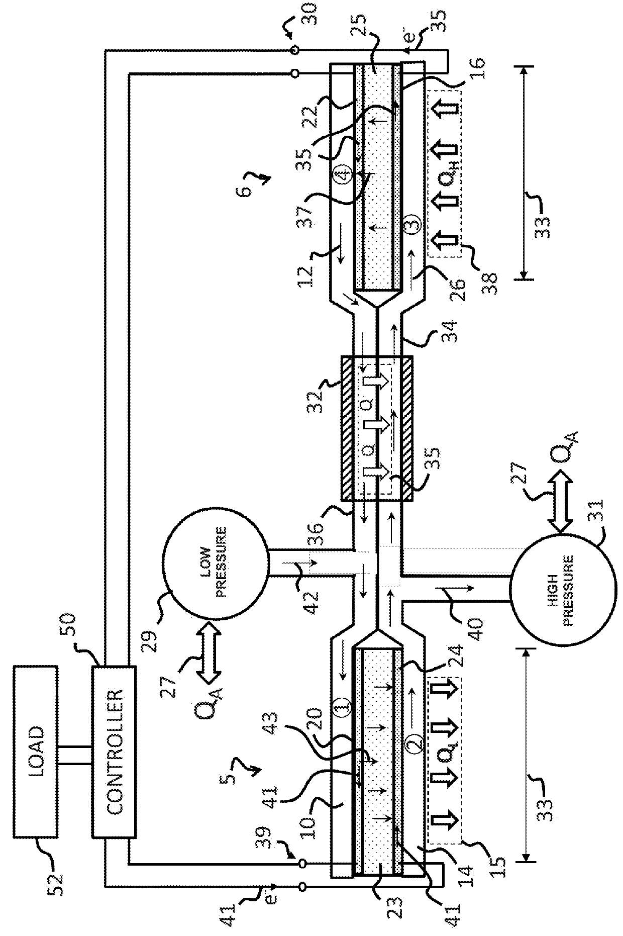
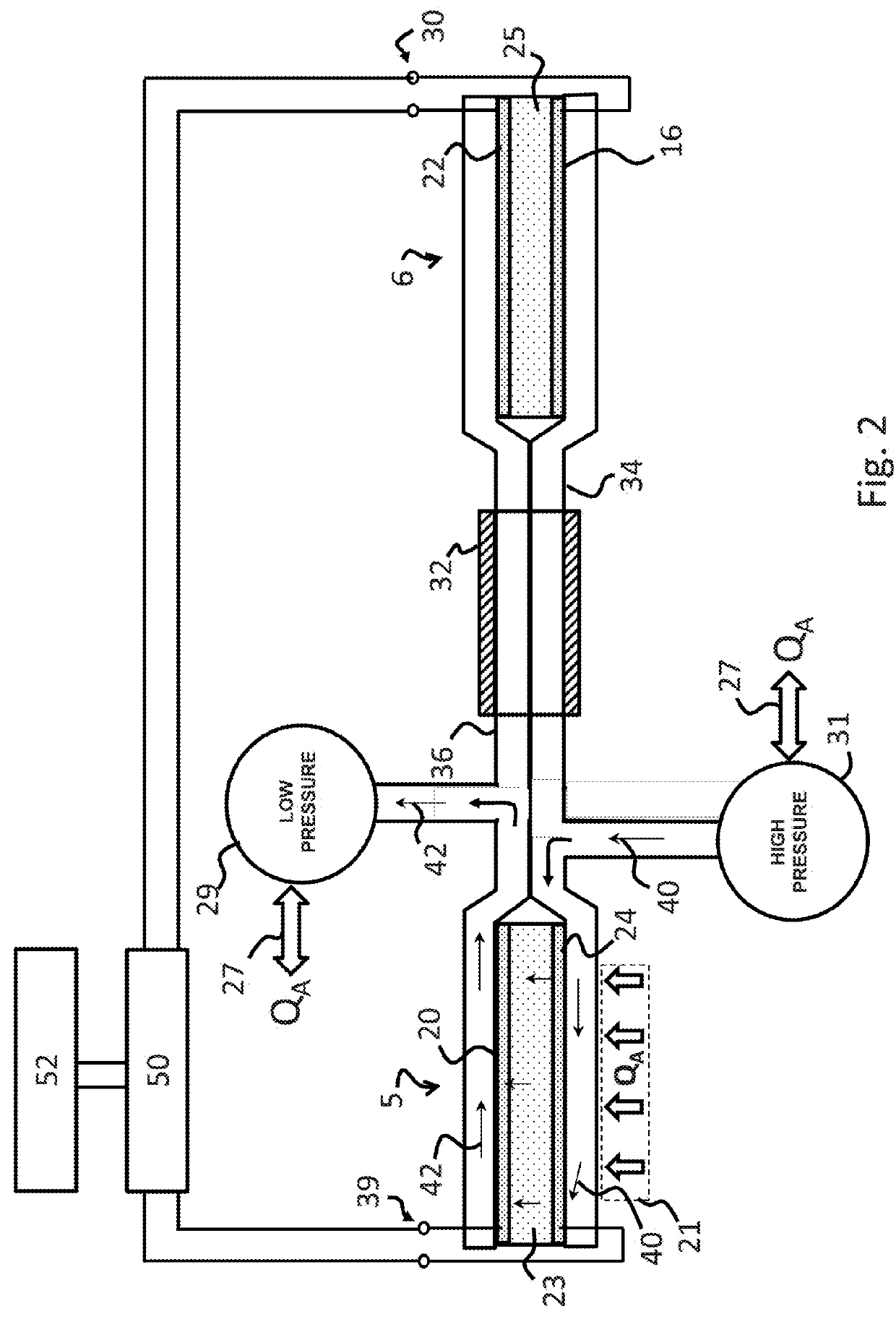
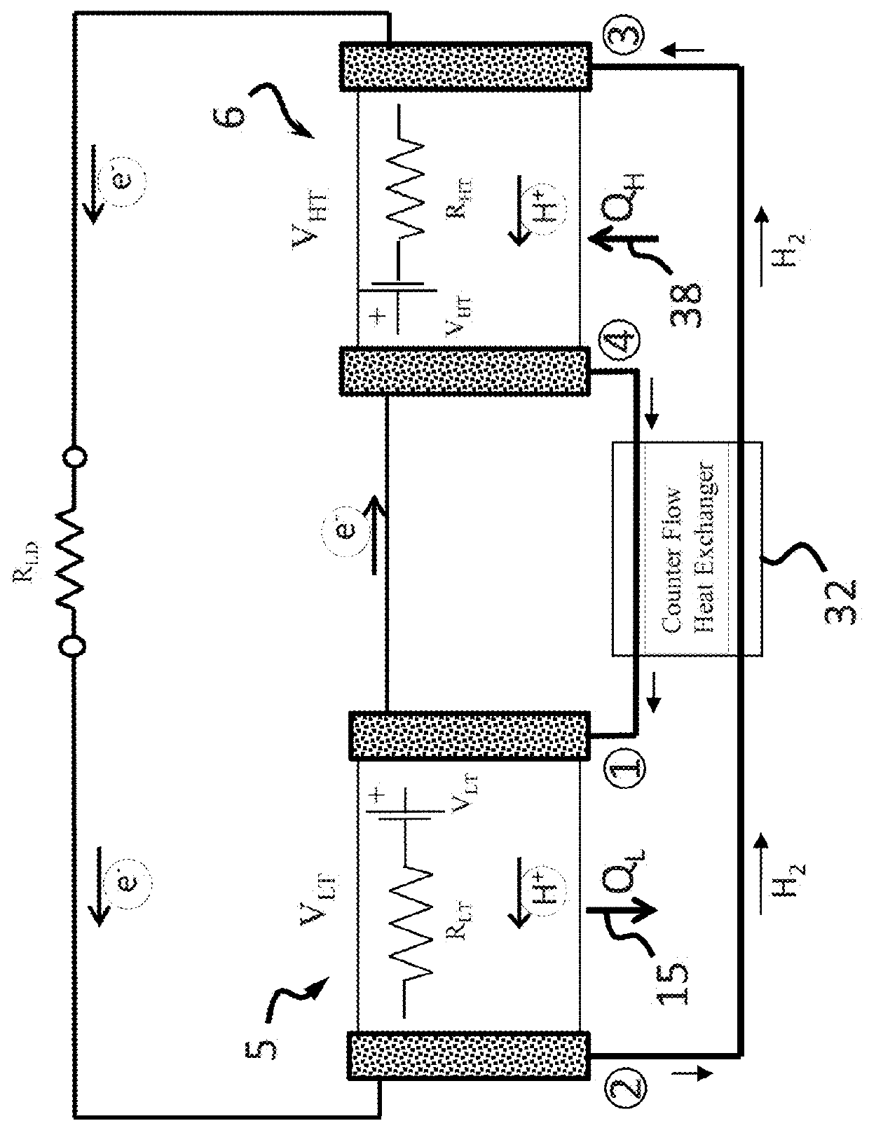
[0049]In one embodiment, the invention relates to an electrochemical direct hea...


PUM


Abstract

An electrochemical direct heat to electricity converter includes a primary thermal energy source; a working fluid; an electrochemical cell comprising at least one membrane electrode assembly including a first porous electrode, a second porous electrode and at least one membrane, wherein the at least one membrane is sandwiched between the first and second porous electrodes and is a conductor of ions of the working fluid; an energy storage reservoir; and an external load. The electrochemical cell operates on heat to produce electricity. When thermal energy available from the primary thermal energy source is greater than necessary to meet demands of the external load, excess energy is stored in the energy storage reservoir, and when the thermal energy available from the primary thermal energy source is insufficient to meet the demands of the external load, at least a portion of the excess energy stored in the energy storage reservoir is used to supply power to the external load.

Description

CROSS-REFERENCE TO RELATED APPLICATIONS[0001]This application claims priority to U.S. Provisional Patent Application No. 62 / 130,227, filed Mar. 9, 2015, and U.S. Provisional Patent Application No. 62 / 219,977, filed Sep. 17, 2015, the disclosures of which are herein incorporated by reference.BACKGROUND OF THE INVENTION[0002]The present invention relates to an improved Johnson Thermo-Electrochemical Convertor (JTEC) with integrated thermal energy storage using metal hydride materials.[0003]The need for energy systems that are capable of both electrical energy generation and energy storage is well understood. Typically power generation systems have production profiles that are different from the energy demand profile. For example, coal power plants optimally produce power at a steady, continuous level. However, the demand for power from coal plants generally has two peaks, one in the morning and one in the evening. Demand for power during the day is higher than nighttime demand. Regard...

Claims


Application Information

Patent Timeline
IPC IPC(8): H01M14/00H01M4/38F25B41/02H01M8/18F25B41/10
CPCH01M14/005H01M4/383F25B41/02H01M8/18H01M8/04014H01M8/04089H01M8/04216H01M2250/40F25B27/00F25B41/10F25B9/14Y02E60/10Y02E60/50
Inventor JOHNSON, LONNIE G.
Owner JTEC ENERGY INC
Why Eureka
Try Eureka