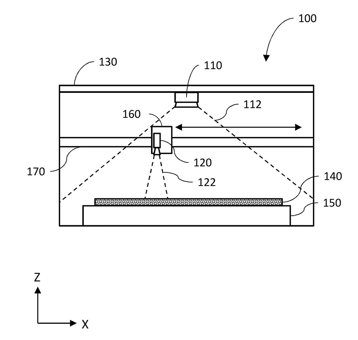
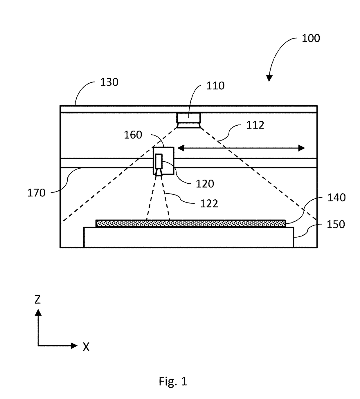
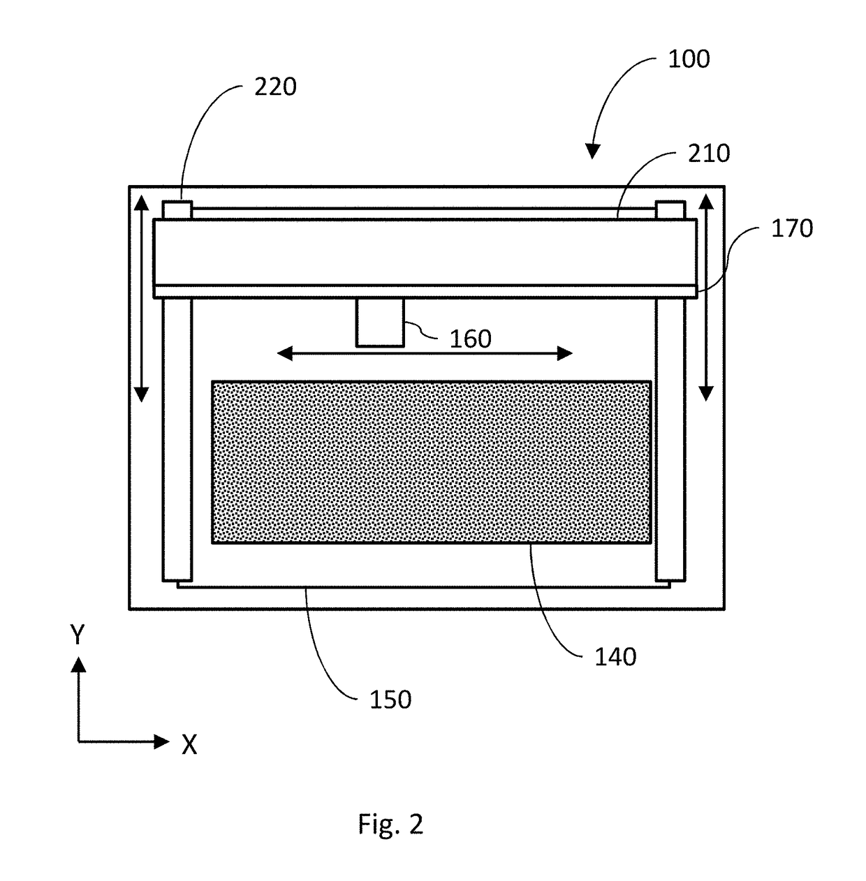
While
laser cutter / engravers share some common features with CNC machines, they have many differences and present particularly challenging design constraints.
A laser cutter / engraver is subject to regulatory guidelines that
restrict the egress of
electromagnetic radiation from the unit when operating, making it challenging for light to enter or escape the unit safely, for example to view or
record an image of the contents.
The beam of a laser cutter / engraver is easily misdirected, with a small angular deflection of any component relating to the beam path potentially resulting in the beam escaping the intended path, potentially with undesirable consequences.
Airflow is important in laser cutter / engraver designs, as air may become contaminated with byproducts of the laser's interaction with the material such as
smoke, which may in turn damage portions of the machine for example
fouling optical systems.
Unlike most
machining tools, the kerf—the amount of material removed during the operation—is both small and variable depending on the material being processed, the power of the laser, the speed of the laser, and other factors, making it difficult to predict the final size of the object.
Also unlike most
machining tools, the output of the laser cutter / engraver is very highly dependent on the speed of operation; a momentary slowing can destroy the workpiece by depositing too much laser energy.
This limitation is modeled in the motion planner and affects the motion plan.
Error conditions can be identified, such as if a
foreign body has been inadvertently left in the CNC machine 100, the material has been inadequately secured, or the material is reacting in an unexpected way during
machining.
In some implementations,
image processing capability can be performed by the CNC machine 100, but with limited speed.
One example of this can be where the onboard processor is slow and can run only simple algorithms in real-time, but which can run more complex analysis given more time.
In another example, if the machine is a laser cutter / engraver and activating the laser causes a camera located in the head to become overloaded and useless, footage from that camera may be discarded when it is unavailable.
In another example, recording of video might cease if an error condition is detected, such as the lid being opened unexpectedly during a machining operation.
If any required connections are broken or operating at insufficient speeds, the
machining process could be slowed, malfunction, or cease altogether.
For example, if a CNC machine 100 is receiving instructions from a remote source and the connection becomes slow, the machine could become stuck on a step or between steps, causing damage to the CNC machine 100 or to the material 140 being processed.
By comparison, for other systems lacking this feature, if a
cutting operation was interrupted abruptly (e.g. the laser suddenly switched off in the middle of a
cut), it could be difficult or impossible to resume the operation in exactly the same manner so as to make the interruption undetectable in the final product.
Coolant temperature can also indicate problems in, for example, the
laser tube, the power supply, a fire in the unit, ambient temperatures above the operating envelope, etc.
For example, if the motor current is higher than forecasted, the motor may be damaged, blocked, or in need of
lubrication.
If the sound is not heard, this can indicate a possible component failure.
In other implementations, if a sound is detected, but does not agree with an expected audio waveform, this can also indicate a possible component failure or anomalous condition.
If the
drill bit gets stuck, then there can be no sound coming from the drilling area, but there may be unusual sounds coming from the
drive motor.
A sudden change in light entering the device unanticipated by an
active motion plan, for instance, may be indicative of the lid of the device being opened and thus be cause for halting an activity or triggering a controlled shutdown.
This is particularly challenging for CO2 lasers, which emit light in the
far infrared, where it is not visible with most commonly available cameras or photodiodes.
The anomaly could result from, for example, a mis-aligned mirror, a block in the beam path, a critical component removed from the
system, or a
laser tube failure.
This is a particularly important failure mode to detect because if the beam is reflected so that it does not enter the head as designed, it could be hazardous.
This is normally accomplished with a switch (a ‘
limit switch’) that must be actuated by physical contact; a common cause of damage to CNC machines is switch failure, causing motors to turn indefinitely, damaging the
system.
The position sensors can detect conditions such a shaking, jolts, or other impacts, that can be either abnormal for expected machine operation, or exceed tolerances of the connected components.
Material, when
cut, engraved, turned, or the like, gets hot and there can be burning or scoring around the area worked.
For example, in one implementation, a
smoke detector can determine that there is too much
smoke, suggesting the presence of an uncontrolled fire.
In another example, if a CPU is reading a temperature higher than forecast, it may be a sign of a different anomaly, for example a bug that is causing additional unwanted program operations, causing the
chip to heat more than expected.
A sudden change in temperature in the device unanticipated by an
active motion plan, for instance, may be indicative of a fan stopping and thus be cause for halting an activity or triggering a controlled shutdown.
This kind of
anomaly detection is more difficult, as characteristic profiles of anomalies generally need to be determined, sensors chosen and aligned carefully, and anomalous events and standard events scrutinized to be able to reliably differentiate between the two.
This phenomenon, called “skipping a step”, is common when the mechanical systems become clogged or jammed.
However, arduous experimentation is required to determine the precise set of acceleration parameters that indicate a missed step as opposed to other forces that made more typically be present.
For example, if the
accelerometer is not perfectly placed and aligned at the factory, then some of the forces will appear in the wrong axis, and the “missed step” may not be detectable via the determined
algorithm.
Both of the prior steps attempt to anticipate the nature of the anomaly; and by their very nature, anomalies are difficult to predict, and a failure means a “false negative”—an anomaly that goes undetected.
This is not true if another subsystem—for example a fan, which is turned on without knowledge of the motion planner—affects the sensor, for example by causing vibrations that are transmitted through to the laser head.
However, a study of returned units and their vibration signatures may find that in fact vibrations over a different,
lower threshold indicate a
high likelihood of failure in the future.
1) Burn marks, melting, or other material issues can require a different approach to machining, for example, reduced power, multiple low-power passes, masking, etc., or simply using a different material.
2) Parts falling under the grate: If the material is placed on rails, a hex grid, or other surface to keep it from sitting on the bottom plate, a common situation with lasers, the material may fall down when cut free. The material can then slide under other material and be cut twice, or if further cuts are to be made on the material, they can be out of focus because the material has fallen down.
3)
Cut failure: If something interrupts the beam, the laser fails, or other problems occur, this can be detected by the cameras.
4)
Cut power lower than expected: If there is a
software or hardware fault and the output power is less than expected, there are a number of visual cues that can be apparent: marks on the material, inadequate penetration of the material, in the case of a CNC bit stalling (bit not turning).
5) Wrong settings for material: The calibration process (described elsewhere in this application) means that the
system knows what to expect from various power levels and speeds; if these are absent, it can be that the wrong material is loaded. The operator can be notified and the new material can be calibrated.
6) Material that has already been cut is
curling up because of heat: This often happens with leather and can cause subsequent cuts to be misaligned. In this case, the cut could be paused and the operator notified to hold the material down, for example, with tape or magnets.
7) Material that has been cut loose blows away and so cannot be subsequently cut: This is often a problem with paper or other light, thin materials. When
cutting concentric circles, if the outer circle is cut first, the paper may be blown away from exhaust
airflow before the inner circle can be cut.
8) Similar to the above, when
scrap pieces are cut out of a lightweight material such as paper,
airflow can blow them into an area that will be cut later. Unlike the previous case, in this case the paper is
scrap, but it may blow in the way of the laser. If this occurs, the laser power may be attenuated by the
scrap and it may not cut through the material properly.
In some cases the system may be able to determine that there is a problem but be unable to diagnose it based on non-image sensors.
Certain circumstances could cause a fire to occur in the cutting area.
However, this can exacerbate a large fire.
A
common source of problems in CNC machines are materials inadvertently left in the machining area, for example a tool left on the
bed of the CNC machine 100.
Finally, a common cause of failure in
CNC milling is instructions that cause the mill to collide with the material being worked on.
For example, if the bit attempts to move to an area occupied by material, it will collide with the material, potentially inflicting serious damage.
However, if the material is a different shape than the
CAM software assumes, then a collision can occur anyway.
A hard shutdown can sometimes do more damage than the condition that triggered it.
A machine bit can break, a thermal gradient on an optic can be exceeded, a project in progress can be left in an unsafe or partially completed state that would be difficult to resume, etc.

