Steel piston crown and/or combustion engine components with dynamic thermal insulation coating and method of making and using such a coating

a technology of dynamic thermal insulation and combustion engine, which is applied in the direction of superimposed coating process, machines/engines, mechanical equipment, etc., can solve the problems of thermal loss through the combustion chamber, eventual spalling and failure of the ceramic layer, and about 4% to 6% of available fuel energy loss, etc., to achieve the effect of improving the thermal barrier coating

Active Publication Date: 2018-05-10
TENNECO
View PDF5 Cites 16 Cited by
  • Summary
  • Abstract
  • Description
  • Claims
  • Application Information

AI Technical Summary

Benefits of technology

[0008]One aspect of the invention provides a piston with an improved thermal barrier coating for use in an internal combustion engine. The piston comprises a body portion including a crown presenting a combustion surface, and the thermal barrier coating is applied to the crown. According to one embodiment, the thermal

Problems solved by technology

Thermal losses through the combustion chamber can be problematic under these increased demands.
Typically, about 4% to 6% of available fuel energy is lost as heat through the piston into the cooling system.
However, ceramic is inherently porous and the combustion gases can pass through the ceramic layer and oxidize the metal layer causing a failure at the ceramic/metal layer interface and eventual spalling and failure of the ceramic layer.
There is also a mismatch in the thermal expansion coefficients of the ceramic and metal layer, further adding to the potential delamination and spalling of the ceramic layer over time.
This material, when used alone, can suffer destabilization through thermal effects a

Method used


Image

  • Steel piston crown and/or combustion engine components with dynamic thermal insulation coating and method of making and using such a coating
  • Steel piston crown and/or combustion engine components with dynamic thermal insulation coating and method of making and using such a coating
  • Steel piston crown and/or combustion engine components with dynamic thermal insulation coating and method of making and using such a coating

Examples


Embodiment Construction

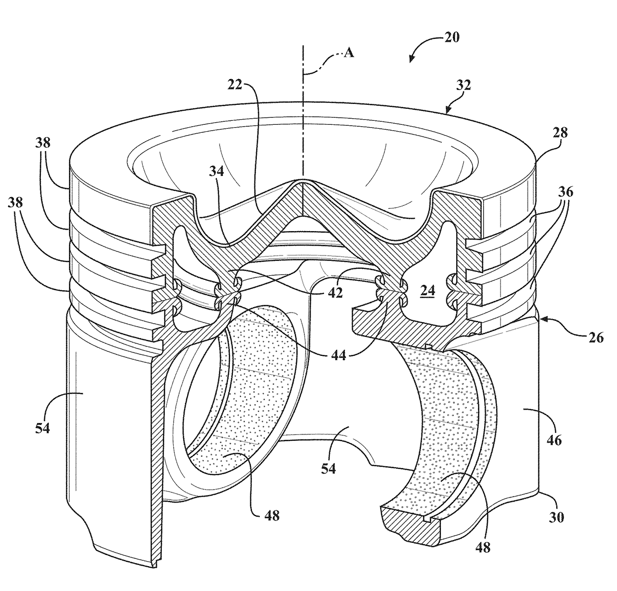
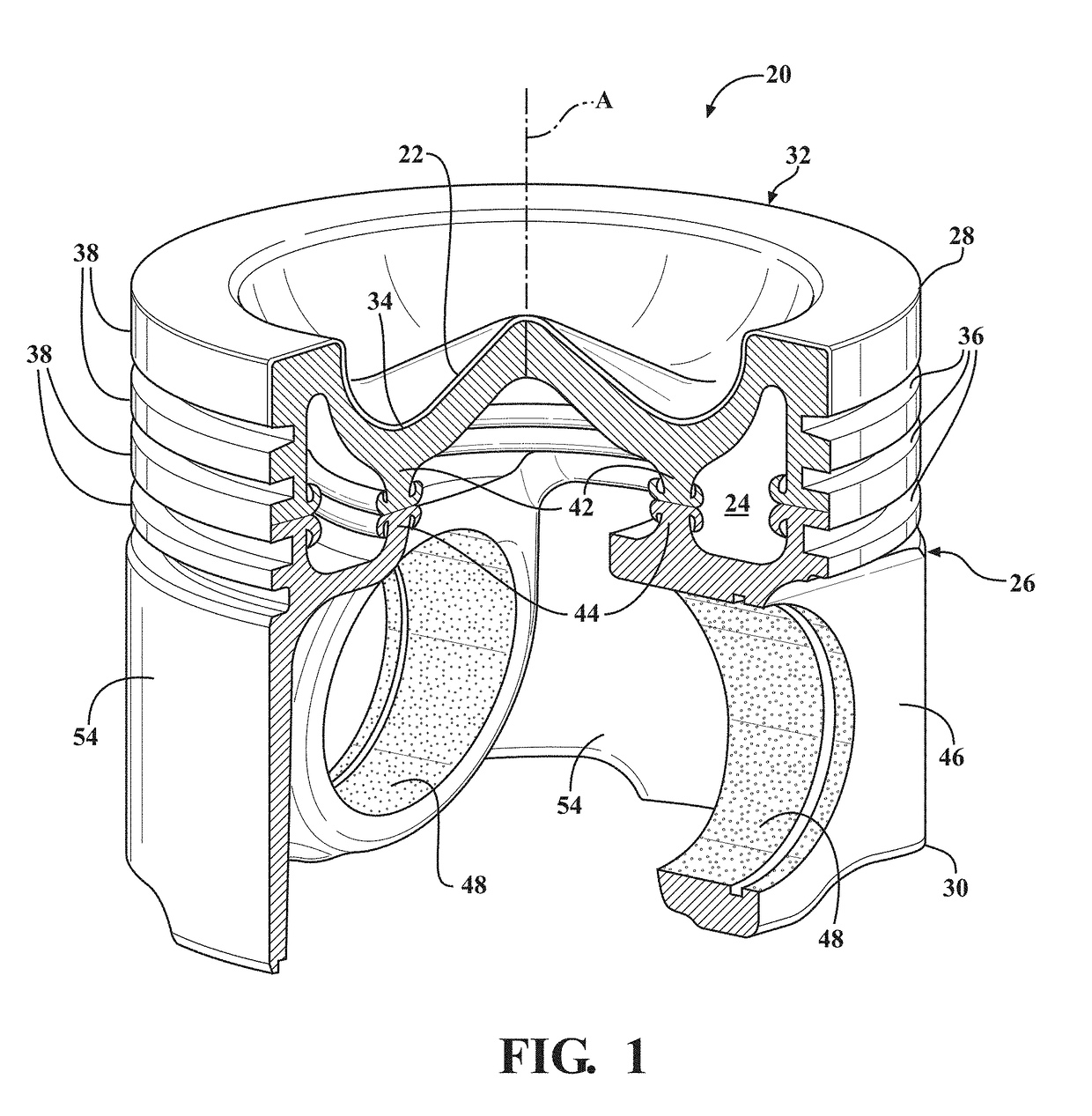
[0021]One aspect of the invention provides an engine component, such as a piston 20, with a thermal barrier coating 22 for use in an internal combustion engine, such as a heavy duty diesel engine or alternatively a gasoline engine. The thermal barrier coating 22 reduces heat loss to the cooling system and thus improves engine efficiency. The thermal barrier coating 22 is also more cost effective and stable, as well as less susceptible to chemical attacks, compared to other coatings used to insulate pistons.

[0022]According to an example embodiment shown in FIG. 1, the thermal barrier coating 22 is applied to the piston 20. However, various different components of the internal combustion engine 20 can be coated with the thermal barrier coating 22. The example piston 20 is designed for use in a heavy duty diesel engine and exposure to combustion gases, but the thermal barrier coating 22 can be applied to other types of pistons, and also to other components exposed to a combustion chamb...


PUM

PropertyMeasurementUnit
Lengthaaaaaaaaaa
Lengthaaaaaaaaaa
Thicknessaaaaaaaaaa

Abstract

A piston for an internal combustion engine is provided. The piston includes a thermal barrier coating applied to a crown formed of steel. According to one embodiment, a bond layer of a metal is applied to a combustion surface of the crown, followed by a mixed layer of metal and ceramic with a gradient structure, and then optionally a top layer of metal. The thermal barrier coating can also include a ceramic layer between the mixed layer and top layer, or as the outermost layer. The ceramic includes at least one of ceria, ceria stabilized zirconia, yttria, yttria stabilized zirconia, calcia stabilized zirconia, magnesia stabilized zirconia, and zirconia stabilized by another oxide. The thermal barrier coating is applied by thermal spray, HVOF, or wire arc spraying. The thermal barrier coating preferably has a thickness less than 200 microns and a surface roughness Ra of not greater than 3 microns.

Description

CROSS-REFERENCE TO RELATED APPLICATION[0001]This U.S. continuation-in part patent application claims priority to U.S. provisional patent application no. 62 / 578,105, filed Oct. 27, 2017 and U.S. utility patent application no. 15 / 354,001, filed Nov. 17, 2016, which claims priority to U.S. provisional patent application no. 62 / 257,993 filed Nov. 20, 2015, the contents of which are incorporated herein by reference in their entirety.BACKGROUND OF THE INVENTION1. Field of the Invention[0002]This invention relates generally to engine combustion components for internal combustion engines including pistons for internal combustion engines, and methods of manufacturing the same.2. Related Art[0003]Modern heavy duty diesel engines are being pushed towards increased efficiency under emissions and fuel economy legislation. To achieve greater efficiency, the engines must run hotter and at higher peak pressures. Thermal losses through the combustion chamber can be problematic under these increased ...

Claims


Application Information

Patent Timeline
IPC IPC(8): F02B77/11F02F3/00F02F3/14F02F3/26C23C4/129C23C4/131C23C4/134
CPCC23C4/131C23C4/134C23C4/18C23C28/36C23C28/32C23C28/345F02F3/0084F02B77/11F02F3/14F02F3/26C23C4/129F02F3/12F02F2003/0061F05C2251/048C23C4/02C23C28/321C23C28/3215C23C28/3455C23C4/11C23C4/073
Inventor LINETON, WARRAN BOYD
Owner TENNECO
Why Eureka
Try Eureka