
Virtual synchronous inverter with fast transient inrush fault currents restraining method thereof

a virtual synchronous inverter and fault current technology, applied in the field of short circuit fault inrush transient current restraining type virtual synchronous inverters, can solve the problems of limiting the further popularization endangering the safe and reliable power supply of the grid, and increasing the cost of virtual synchronous inverters, etc., to achieve rapid restraint of inrush current and low voltage

Active Publication Date: 2018-05-24
HUNAN UNIV
View PDF3 Cites 57 Cited by
  • Summary
  • Abstract
  • Description
  • Claims
  • Application Information

AI Technical Summary

Benefits of technology

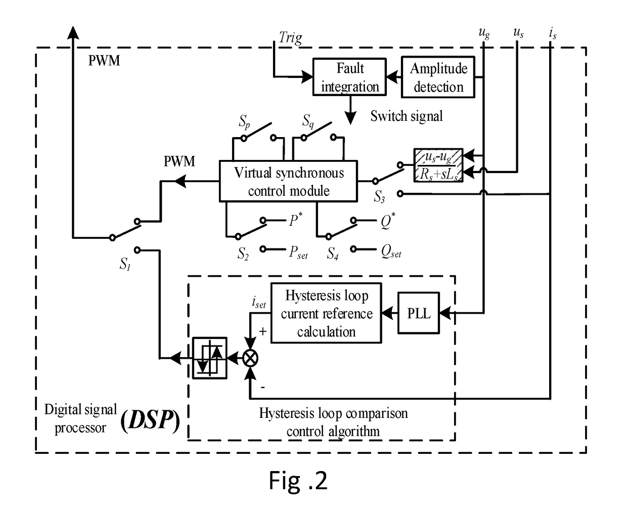
The present invention is a combination of two control methods: virtual synchronous inverting control and hysteresis compassion control. When the grid voltage decreases dangerously, the virtual synchronous inverter quickly switches to the hysteresis control system to rapidly restrict the inrush current. This ensures that the inverter is not removed from the grid while still providing voltage support to it. Once the fault is cleared, the virtual synchronous inverter returns to its normal operation mode without inrush current. The invention has the benefits of virtual synchronous inverting control while also being able to restrain the inrush current when a grid fault occurs.

Problems solved by technology

Thus, cost of the virtual synchronous inverter is increased, which will limit the further popularization of the virtual synchronous inverter.
When a short circuit fault occurs in the grid, the conventional method is to disconnect the inverter from the grid directly to ensure the safety of the inverter, which endangers a safe and reliable power supply of the grid.
The safe of the inverter is thus endangered, which demands an inrush transient current restraining method for the virtual synchronous inverter in urgent.
However, these researches are focused on the steady-state control and parameters optimization with few considerations on the impact on the inverter when a grid fault occurs.
Actually, the inrush current will endanger the stable operation of the inverter and even be strong enough to destroy the inverter.

Method used


Image

  • Virtual synchronous inverter with fast transient inrush fault currents restraining method thereof
  • Virtual synchronous inverter with fast transient inrush fault currents restraining method thereof
  • Virtual synchronous inverter with fast transient inrush fault currents restraining method thereof

Examples


Embodiment Construction

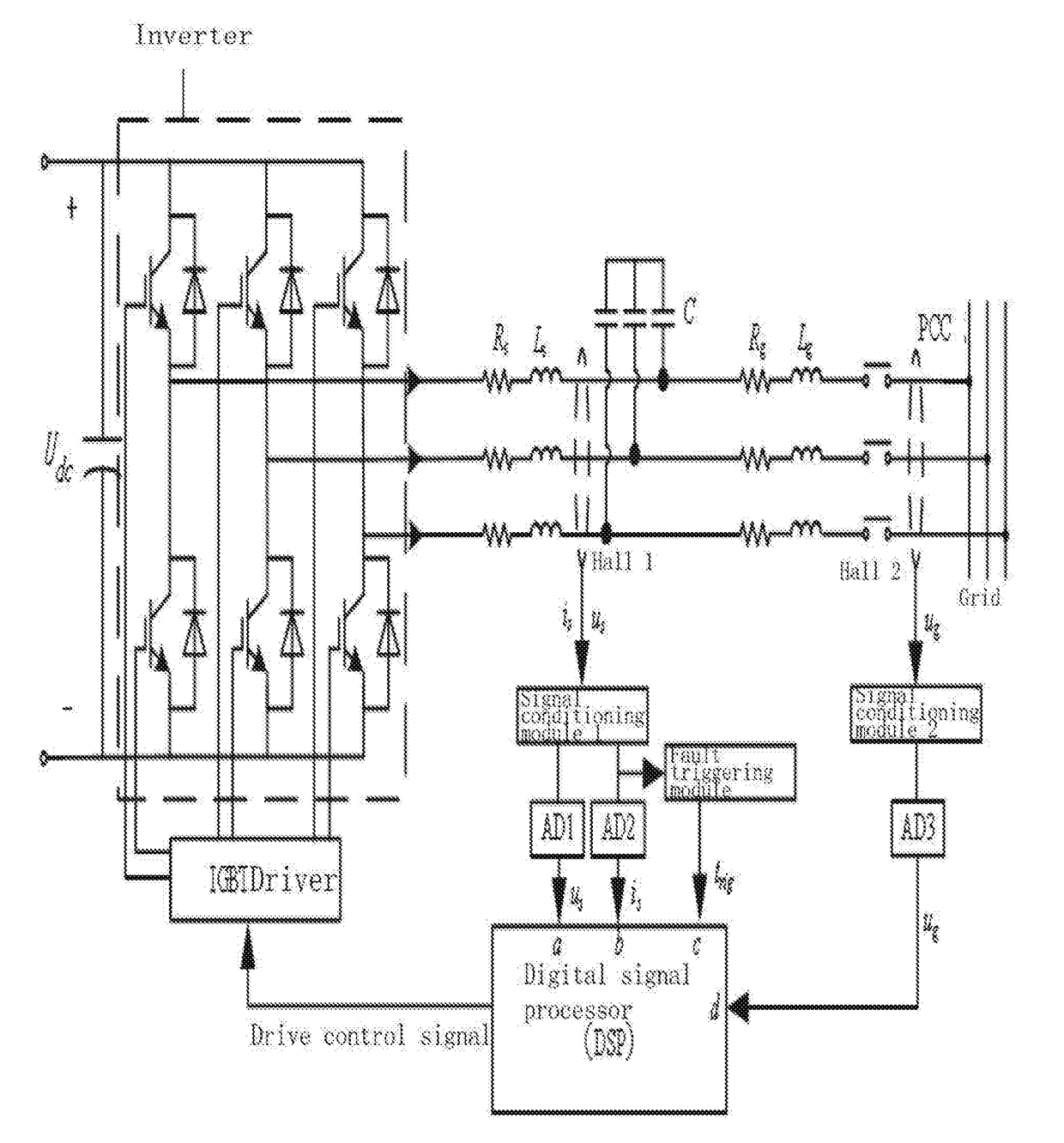
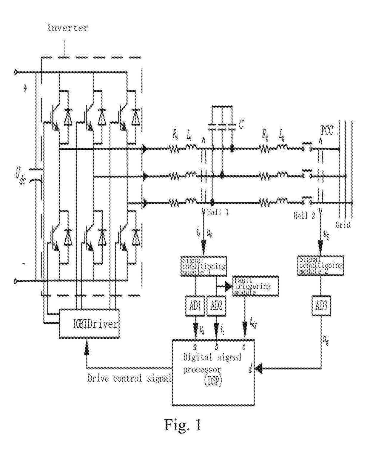
[0029]Referring to FIG. 1 to FIG. 6 of the drawings, the technical solution of a preferred embodiment of the present invention is illustrated, wherein the embodiment described is just a one of the embodiment of the present invention not all. A skilled technician is able to bring up other embodiments without innovative efforts based on the embodiment of the present invention. All the embodiments are within the protection range of the present invention.

[0030]A fault inrush transient current restraining type virtual synchronous inverter, comprising: an information collection module for inverter output voltages and currents, a virtual synchronous inverting control module, a fault detection and synthesize module, a hysteresis comparison control loop module and a post fault clearing switch back grid-tie control module; wherein

[0031]the information collection module for the inverter output voltages and currents collects an output voltage signal of the inverter, an output current signal of ...


PUM


Abstract

A fault inrush transient current restraining type virtual synchronous inverter and thereof is disclosed. The invention solves the problem that a virtual synchronous inverter will be burned due to inrush transient current in an extreme situation of a symmetrical fault occurring on the grid side by setting an information collection module for inverter output voltages and currents, a virtual synchronous inverting control module, a fault detection and synthesize module, a hysteresis comparison control module and a post fault clearing switch back grid-tie control module.

Description

CROSS REFERENCE OF RELATED APPLICATION[0001]This invention claims priority under 35 U.S.C. 119(a-d) to CN 2017100291299, filed Jan. 16, 2017.BACKGROUND OF THE PRESENT INVENTIONField of Invention[0002]The present invention relates to the inverter control technical field, and more particularly to a short circuit fault inrush transient current restraining type virtual synchronous inverter and a control method thereof.Description of Related Arts[0003]With a rapid development of the society, the conflict between an explosive increase in energy demands and a rapid deterioration of the environment arises, which brings more and more attention to the renewable energy such as wind and solar energy. Most of the renewable energy output the electricity in forms of alternative current of varied frequencies or direct current, wherein a DC-AC inverter is necessary for accessing the grid. With a sustaining development of the micro-grid, the need for researches on the safety and reliability of the in...

Claims


Application Information

Patent Timeline
Patent Type & Authority Applications(United States)
IPC IPC(8): H02M1/32H02M7/5387
CPCH02M1/32H02M7/53873H02J3/38H02M7/5387H02M1/325
Inventor SHUAI, ZHIKANGHUANG, WENSHEN, ZHENGWANG, JUNFANG, JUNBINSHEN, CHAOLI, YANG
Owner HUNAN UNIV
Learn More