Method of non-destructive testing a cutting insert to determine coating thickness

a cutting insert and coating technology, applied in the field of cutting inserts, can solve the problems of providing results at various levels of cost, accuracy and time, high equipment and testing costs, and time-consuming sample preparation, and achieve the effect of time and cost-effectiveness

Active Publication Date: 2018-06-21
KENNAMETAL INC
View PDF3 Cites 8 Cited by
  • Summary
  • Abstract
  • Description
  • Claims
  • Application Information

AI Technical Summary

Benefits of technology

[0010]The problem of measuring the thickness of a single or multilayer coating of a cutting insert in a continuous flow operation in a timely and cost-effective manner is solved by using a source of electromagnetic energy, such as a pic...

Problems solved by technology

Due to their inherent differences, each method provides results at various levels of cost, accuracy and time.
However, sample preparation is time consuming, which typically takes about forty minutes to prepare the sample and another fifteen minutes to measure the coating thickness.
GDOES provides quick results, but the equipment and testing costs are high.
Due to the amount of time necessary for each of these te...

Method used


Image

  • Method of non-destructive testing a cutting insert to determine coating thickness
  • Method of non-destructive testing a cutting insert to determine coating thickness
  • Method of non-destructive testing a cutting insert to determine coating thickness

Examples


Embodiment Construction

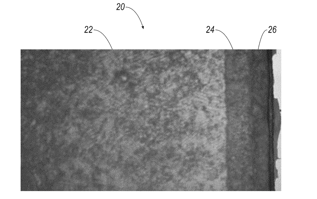
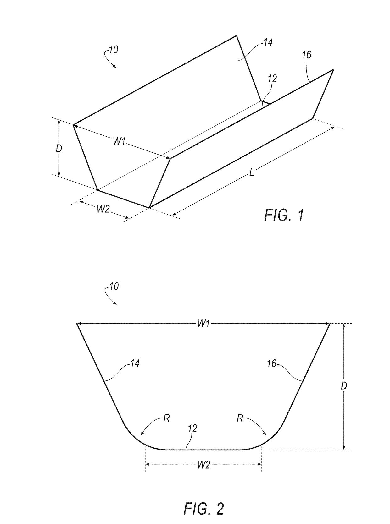
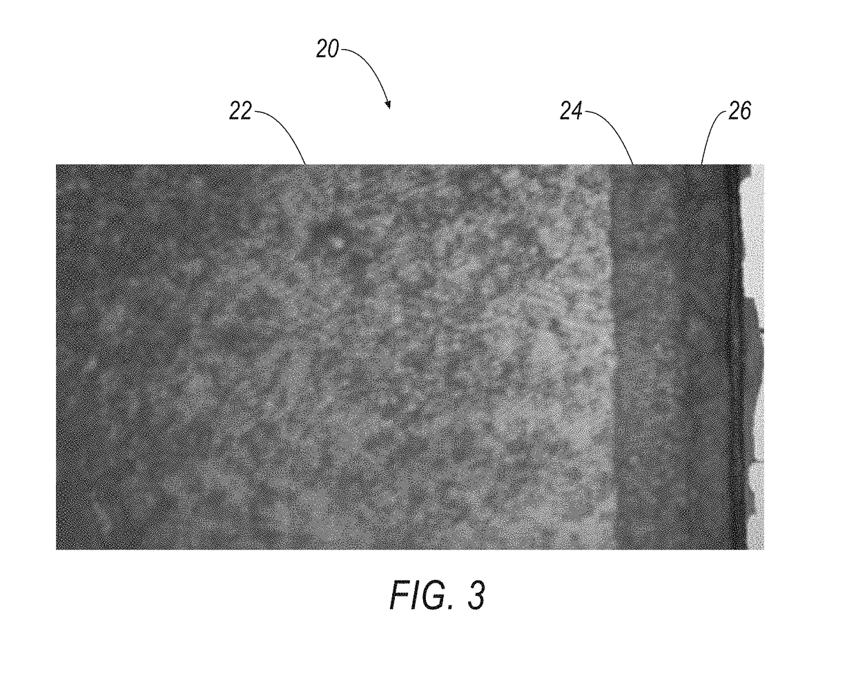
[0024]In general, the non-destructive method of the invention comprises the steps of: 1) using a source of electromagnetic energy, such as a femtosecond laser, and the like, to ablate the surface of the cutting insert to form a geometric feature and expose a cross section of the one or more layers of a coating; and 2) measuring the thickness of the one or more layers by examination of the cross section using conventional microscopy techniques.

[0025]One technique of forming the groove through the one or more coating layers is by using electromagnetic energy, such as a short pulse picosecond laser, short pulse femtosecond laser, and the like. Short pulse lasers have undergone a rapid growth both in capability and application since the advent of chirped pulse amplification. Initially driven by cutting-edge fundamental research, the development of femtosecond lasers has now interlinked with many industrial metrology, research, and clinical applications. Further, by enabling action on ma...


PUM

PropertyMeasurementUnit
Timeaaaaaaaaaa
Timeaaaaaaaaaa
Poweraaaaaaaaaa

Abstract

A method for non-destructive testing a cutting insert to determine coating thickness is disclosed. The method includes the steps of using a source of electromagnetic energy to ablate a surface of the cutting insert to non-destructively form a geometric feature and expose the substrate and each layer of the coating; and measuring the thickness of each layer of the coating. In one example, the geometric feature is a groove with a generally trapezoidal shape. In other examples, the groove can have a U-shape, V-shape, and the like. The thickness of each layer of the coating is determined using focus variation, contrast detection, confocal microscopy, an interferometric microscopy, an imaging interferometric microscopy, or similar technique.

Description

FIELD OF THE INVENTION[0001]In general, the invention relates to a cutting insert and, more particularly, to a method of non-destructive testing of a cutting insert to measure coating thickness of the cutting insert by using electromagnetic radiation to expose each layer of the coating, followed by measuring the thickness of each layer using commercial microscopy techniques, such as focus variation, contrast detection, confocal microscopy, interferometric microscopy, imaging interferometric microscopy, and the like.BACKGROUND OF THE INVENTION[0002]Cutting inserts with one or more layers of coating, for example, thin film physical vapor deposition (PVD), chemical vapor deposition (CVD) and thick hard coatings in the form of single or multilayer architectures has become standard practice for enhancing wear and corrosion resistance in the cutting tool industry. In production, coating quality is related to various aspects, such as: thickness, adhesion to the substrate, hardness, surface...

Claims


Application Information

Patent Timeline
IPC IPC(8): G01B11/06B23K26/40B23K26/0622
CPCG01B11/0616B23K26/40B23K26/0624B23B2228/105B23K2203/166B23B27/14B23K2201/35G01B9/02041G01B11/0675G01B11/0683B23K2101/35B23K2103/166
Inventor KONDAMEEDI, NAVEEN KUMARGEY, CHRISTOPH
Owner KENNAMETAL INC
Why Eureka
Try Eureka