Method and apparatus for determining biometric indicators using multiple fluorescent markers

a biometric indicator and fluorescent marker technology, applied in the field of fluorescence spectrometry, can solve the problems of reducing the survival chance of patients, deteriorating patient condition faster than the indicators may be assessed, and inability to determine the proper course of medical treatment, etc., and achieve the effect of accurate prediction

Inactive Publication Date: 2018-06-28
PHARMACOPHOTONICS INC
View PDF0 Cites 3 Cited by
  • Summary
  • Abstract
  • Description
  • Claims
  • Application Information

AI Technical Summary

Benefits of technology

[0126]The term “time zero” or “T0”, as used herein, is the point in time that the injectate is introduced into the vasculature of the mammalian subject. It may also coincide with the moment in a spectrometric data set that is characterized by the peak fluorescent signal intensity of intravenously injected fluorescent markers (and thus the point of initial analysis for the math). Thus, T0 is used to signify the start of the biometric parameter fluorescent signal analysis. The term “raw ratio” as used herein may be defined as the ratio of fluorescent signal intensities of the two fluorescent tags at T0, i.e. the ratio of the dynamic marker (“small marker”, indicating a smaller molecular weight, or “green marker”, indicating a fluorescent tag emitting in the green spectrum) to the static marker (“larger marker”, indicating a larger molecular weight, or a “red marker”, indicating a fluorescent tag emitting in the red spectrum). An important aspect of the present technology is the use of the raw ratio to determine HCT in an optically dynamic environment.
[0127]It has been found that up to one-half of the small marker is filtered from the blood stream after only about 15 minutes following the initial bolus infusion of a dynamic marker and a static marker, which in some embodiments totals about 3 ml. Accordingly, following the procedure of the present invention, the concentration of the dynamic marker at T0 can be accurately predicted using, for instance, a spectrometric analyzer to measure the concentration of the static marker at 10 to 15 minute intervals as described herein. This is a significant advance since it permits the use of periodic biometric sampling, e.g., sampling the vasculature every 10 to 60 minutes or 3 times over 2 hours (which may be done to calculate plasma volume and GFR), as contrasted to a continuous sampling procedure. Thus the total test time can be shortened to about 1 to 2 hours in duration from about 6 hours required by the current methods. The “sampling” may be conducted in accordance with techniques known in the art, e.g., via blood samples and use of invasive (e.g., venous) or non-invasive (e.g., oral) probes.
[0128]The raw ratio may be used, in turn, to calculate the hematocrit observed at the optical interface of an optical probe, referred to herein as the apparent HCT. The apparent hematocrit obtained from invasive (e.g., venous) probes may be different from a subject's true HCT. This may be attributed to fluid dynamic anomalies occurring near an optical interface inserted in a flowing system. True HCT may be calculated from apparent HCT by applying a correction factor. A correction factor may be in the range of 1 to 10 percent of apparent HCT, and more specifically in the range of 4-5 percent of HCT. A typical calculation of the correction factor is shown in the Examples herein. Thus, a correction function is not necessary when the invention is carried out with non-invasive probes such as oral probes.
[0129]A method for determining a species specific HCT curve may utilize the following components: a calibrated fluorescence detector, a Calibrated Injectate, and a test volume of species specific blood. A procedure may be performed to maintain a constant total test volume and constant concentration of Calibrated Injectate in the test volume while altering the HCT in the test volume.
[0130]A calibrated fluorescence detector is set up and configured to read the fluorescence intensities of the test volume throughout the procedure. A test volume is prepared, with a known HCT (Hcalib), as determined by conventional methods, and a measured total volume (Vt). A known volume of Calibrated Injectate is added to the test volume. A separate volume is created from normal saline and Calibrated Injectate, with an equivalent concentration of Calibrated Injectate added to the test volume. This solution is used to replace removed volume from the test volume during the procedure. A series of repetitive steps is then used to create different HCT levels in the test volume. A volume (x) is removed from the test volume, discarded, and replaced with an equivalent volume (x) of prepared saline solution. The system is allowed to stabilize, and the HCT is calculated at each stage based on the dilution of HCT. The average signal level of a “flat portion” of data at each HCT level tested is determined as shown, where Vt is the total volume in the test set, Ve is the volume exchanged (blood for saline), H0 is the starting HCT (prior to volume exchange) and H′ is the new HCT (post volume exchange). A hematocrit dependent curve is produced where the raw ratio is an input and the apparent hematocrit is the output.
[0131]Invasive, e.g., venous probes suitable for use in the present invention are known in the art. See, e.g., U.S. Patent Publication 2012 / 197136, commonly owned, contents of which are hereby incorporated by reference.

Problems solved by technology

Biometric indicators are valuable tools used by medical practitioners to aid in the diagnosis of a patient, and their ability to determine the proper course of medical treatment is often limited by access to rapid and accurate quantitative biometric information.
While a medical practitioner may prefer to assess multiple biometric indicators prior to deciding on a particular treatment, the patient's condition may deteriorate faster than the indicators may be assessed.
In these situations, medical practitioners are required to make decisions with limited information, potentially decreasing a patient's chance of survival.
While this method is relatively accurate, the blood sample is often sent to a medical laboratory separate from the patient care room for analysis, which may drastically increase the sample processing time and limits its utility in time sensitive medical situations.
While conventional fluorescent injectates used to determine GFR and plasma volume are being developed for human use and have shown favorable biocompatibility, and HCT is often assessed with GFR and plasma volume in certain medical situations, they have not been used to measure HCT due to the dynamic optical properties resulting from the constantly changing concentrations of the dynamic marker used in the injectate.
Noninvasive direct spectrometric methods and devices require the use of multiple optical interfaces and optical conduits at a fixed geometry, resulting in devices that are mechanically rigid and difficult to sterilize.
While fluorescent spectrometric systems are able to measure GFR and plasma volume via a single optical conduit, they are conventionally unable to measure hematocrit due to the constantly changing concentrations of the dynamic markers.

Method used


Image

  • Method and apparatus for determining biometric indicators using multiple fluorescent markers
  • Method and apparatus for determining biometric indicators using multiple fluorescent markers
  • Method and apparatus for determining biometric indicators using multiple fluorescent markers

Examples


example 1

Generation of Calibration Curves

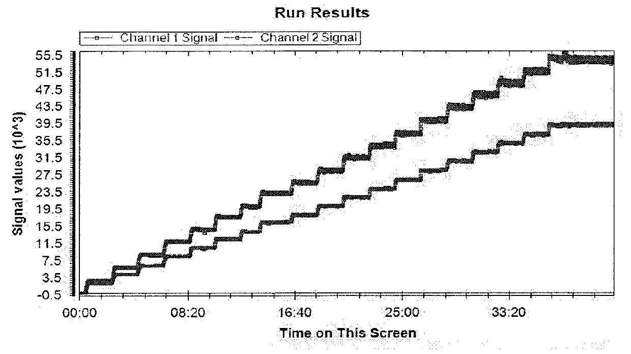
[0139]1. A step dose blood test set is run on a whole blood sample containing two fluorescent markers each having its distinct emission wavelength. An example of the results is shown in FIG. 1 with the upper curve representing the first emission signals from the first fluorescent marker or tag recorded in Channel 1 as the Channel 1 signal, and the second emission signals from the second fluorescent marker or tag recorded in Channel 2 as the Channel 2 signal. As discussed previously, this step dose blood test set can also be generated using one static marker having two fluorescent tags each tag having its distinct emission wavelength. Each fluorescent marker or each fluorescent tag may be referred to as a “fluorescent component” hereafter.

[0140]2. The average signal level of the “flat” or stable portion at each dose step for each fluorescent component is calculated.

[0141]3. Based on the known volume of blood (Vt) used, the known dose of VFI (VD) and th...

example 2

Generation of a Species Specific Hematocrit (HCT) Calibration Curve

[0143]1. A blood test is run with the single dose approach. With a known volume of blood (Vt) and a known HCT of the blood (Hcalib), the volume of saline (VS) needed for the test is calculated.

Vt−VtHcalib=VS   (4)

[0144]2. The blood and the saline are equivalently dosed from the same VFI vial.

[0145]3. A predetermined volume of blood is removed from the test set and discarded. The same volume of dosed saline, as the blood previously removed, is injected back into the test set. This exchange will maintain the concentration of each component as well as the total volume of the test set, but alter the volume of distribution to HCT ratio. This step is repeated numerous times to generate multiple data points at which the volume of distribution and HCT ratio are different.

[0146]4. Each new point is allowed to stabilize before a new point is generated. A new HCT is calculated at each stable point.

(Vt-Ve)(H0)Vt=H′(5)

Where Vt is...

example 3

Determining Various Biometric Indicators

[0151]When a test is run on a subject, the “batch” of VFI must be known because the signal calibration and HCT calibration curves used for interpretation must be based on the same “batch” of VFI given to the subject.

[0152]1. From a test data sample of FIG. 5, the raw ratio at T0 (RT0) and the average stable Component 2 (FD003) signal level (Savg) are extracted. The lower curve in FIG. 5 represents Channel 1 signals, and the upper curve represents Channel 2 signals.

[0153]2. Using the raw ratio at T0 (RT0), the apparent HCT of the subject is calculated from the Ratio vs HCT Calibration Curve.

RT0=KH−q   (10)

H=Happ   (11)

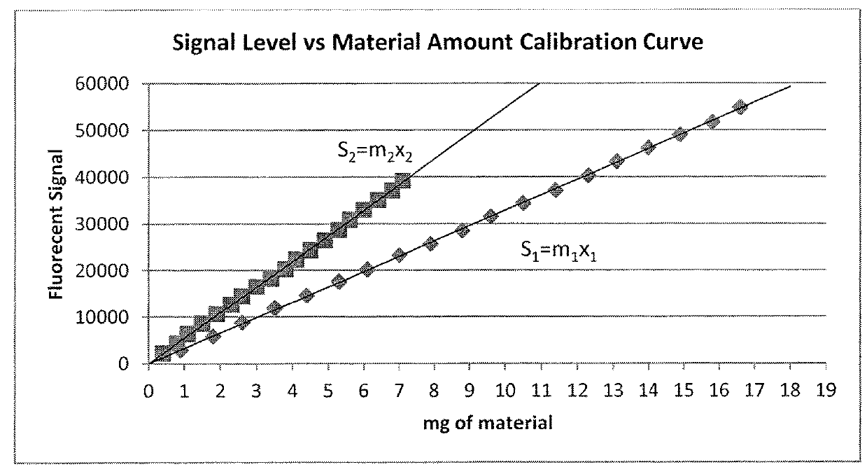
[0154]3. Using the calculated apparent HCT and the Signal Level vs. Material Amount Calibration Curve; the amount of correction, C, is calculated and applied to the average signal level component.

[0155]From Equation 7:

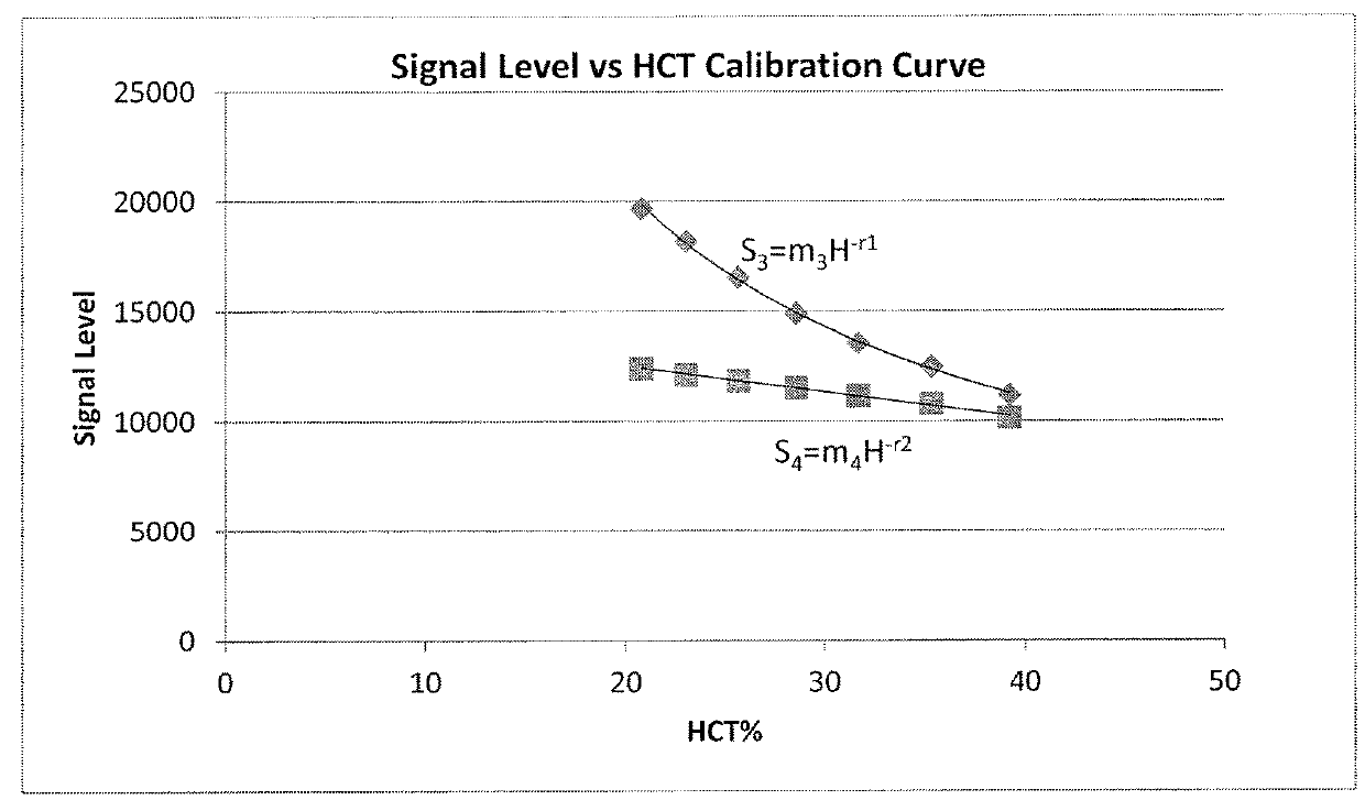
Scalib=m4Hcalib−r   (12)

Sapp=m4Happ−r   (13)

If Happcalib then Scalib / Sapp

If Happ>Hcalib then Sapp / Scalib

Scalib / S...


PUM

PropertyMeasurementUnit
molecular weightaaaaaaaaaa
molecular massaaaaaaaaaa

Abstract

Disclosed are methods for determining biometric indicators such as plasma volume, hematocrit and glomerular filtration rate, in mammalian subjects such as humans. The methods utilize a plurality of fluorescent tags having distinct fluorescent characteristics, which may be associated with a single static molecule, or wherein the static molecule is labeled with a fluorescent tag and a dynamic molecule is labeled with another fluorescent tag. One or more measurements of the intensities of the fluorescent emissions are taken subsequent to introduction of an injectate which contains the fluorescent tags, which can be taken using a probe or via a blood or plasma sample. Compositions and apparatuses for practicing the methods are also disclosed.

Description

CROSS REFERENCE TO RELATED APPLICATION[0001]This application claims the benefit of U.S. Provisional Patent Application No. 62 / 183,787, filed Jun. 24, 2015, the contents of which are incorporated herein by reference in their entirety for all purposes.FIELD OF THE INVENTION[0002]Disclosed are compositions and methods for collecting biometric information from a mammalian subject, and preferably a human subject. More particularly, the disclosure is directed to fluorescent spectrometric methods for quantifying hematocrit and other biometric indicators of a subject by repeatedly introducing a calibrated injectate including one or more fluorescent markers into the vascular system of the subject, and monitoring the emission intensities of the fluorescent marker(s) over a period of time.BACKGROUND OF THE INVENTION[0003]Biometric indicators are valuable tools used by medical practitioners to aid in the diagnosis of a patient, and their ability to determine the proper course of medical treatme...

Claims


Application Information

Patent Timeline
Patent Type & Authority Applications(United States)
IPC IPC(8): G01N33/58A61B5/00A61B5/02A61B5/145
CPCG01N33/582A61B5/0071A61B5/02028A61B5/14535A61B2560/0233
Inventor MEIER, DANIEL J.SANDOVAL, JR., RUBEN M.REILLY, ERINN
Owner PHARMACOPHOTONICS INC
Why Eureka
Try Eureka