Vibrating screening feeder and method of use

a technology of vibrating screen and feeder, which is applied in the direction of grain treatment, transportation and packaging, light and heating equipment, etc., can solve the problems of high energy loss of electromagnetic vibrators, limited feeders, and no success of these types of vibrators

Inactive Publication Date: 2018-07-12
KINERGY
View PDF10 Cites 25 Cited by
  • Summary
  • Abstract
  • Description
  • Claims
  • Application Information

AI Technical Summary

Benefits of technology

[0020]A continuous, steady flow of the supply of the incoming bulk solid such as coal, ore, wood waste, or the like is required as feed material for optimal control and screening performance of the feeding and screening system. It is recommended that the vibrating screening feeder be installed under the outlet of a storage bin or silo or surge bin. The outlet of the steady feed source must be interfaced with the vibrating screening feeder inlet chute that connects to the feed bin. The chute typically includes a baffle of 30 to 60 degrees and preferably about 45 degrees to help convert the vertical feed flow into the inlet to a horizontal or near horizontal flow and spread across the full width of the vibrating screen feeder feed plate. The screen media is usually woven wire of perforated plate with longitudinal side clamps, flap plastic squares or any standard screen media. Three screening decks are typically used in the apparatus; however, it is contemplated that additional decks may be added. The passed “unders” (under sized particles) collecting pan is disposed beneath the screening plates and extends the full width and length of the screen for collecting and conveying all of the passed “unders” to an outlet located near to the end of the screen. The collecting pan includes an outlet for discharging the “passed unders” located near the end of the screens and can be full width or converging. The means for powering the vibrating screening feeder is accomplished by motorized an AC motor rotating unbalanced eccentric weights combined with sub-resonant tuned steel coil drive springs which are attached to the end of a longitudinal counterbalanced support base which is a longitudinal structure which can be cut into sections that are bolted together if necessary. The instant invention concentrates and nests the steel drive coils in selected positions or locations connecting the screening unit to the longitudinal counterbalance support base.

Problems solved by technology

However, in this type of device the vibrations per minute used are generally above 1800 cycles per minute and have relatively short strokes with the result that such feeders are limited to bulk materials of the more free-flowing type as distinguished from those which are characterized as damp or viscous.
There have been many attempts, in vibratory feeders, to utilize some form of adjustable feed rate control using electrical phenomena, but to date none of these have been successful for a number of reasons.
The electromagnetic type vibrators have high energy losses and are restricted to essentially high frequency and short stroke combinations.
Low frequency, long stroke devices have been conceived that utilize adjustable frequency A.C. drives, multi-speed, and / or multi-winding A.C. motors, or adjustable voltage D.C. drives. have met with success because of high initial cost, and the cost of maintenance due to brush wear, commutator problems and the like.
When fuel is scarce because of shortages uncleaned ROM coal and the waste coals such as culm, gob, silt, or high moisture “wet” coal are burned, especially in countries having economic difficulties.
Density and moisture content are difficult to control.
These units have inherent disadvantages such as difficulty of changing or repairing motor drives and large energy consumption.
Another common problem with vibrating screens occurs when screens become jammed or clogged with aggregate material.
This clogging slows or stops throughput causing costly shutdown for screen cleaning and unclogging.

Method used


Image

  • Vibrating screening feeder and method of use
  • Vibrating screening feeder and method of use
  • Vibrating screening feeder and method of use

Examples


Embodiment Construction

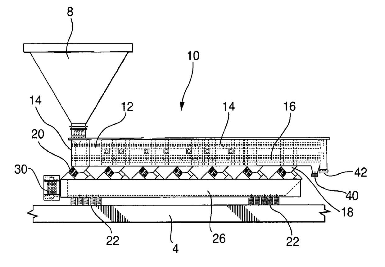
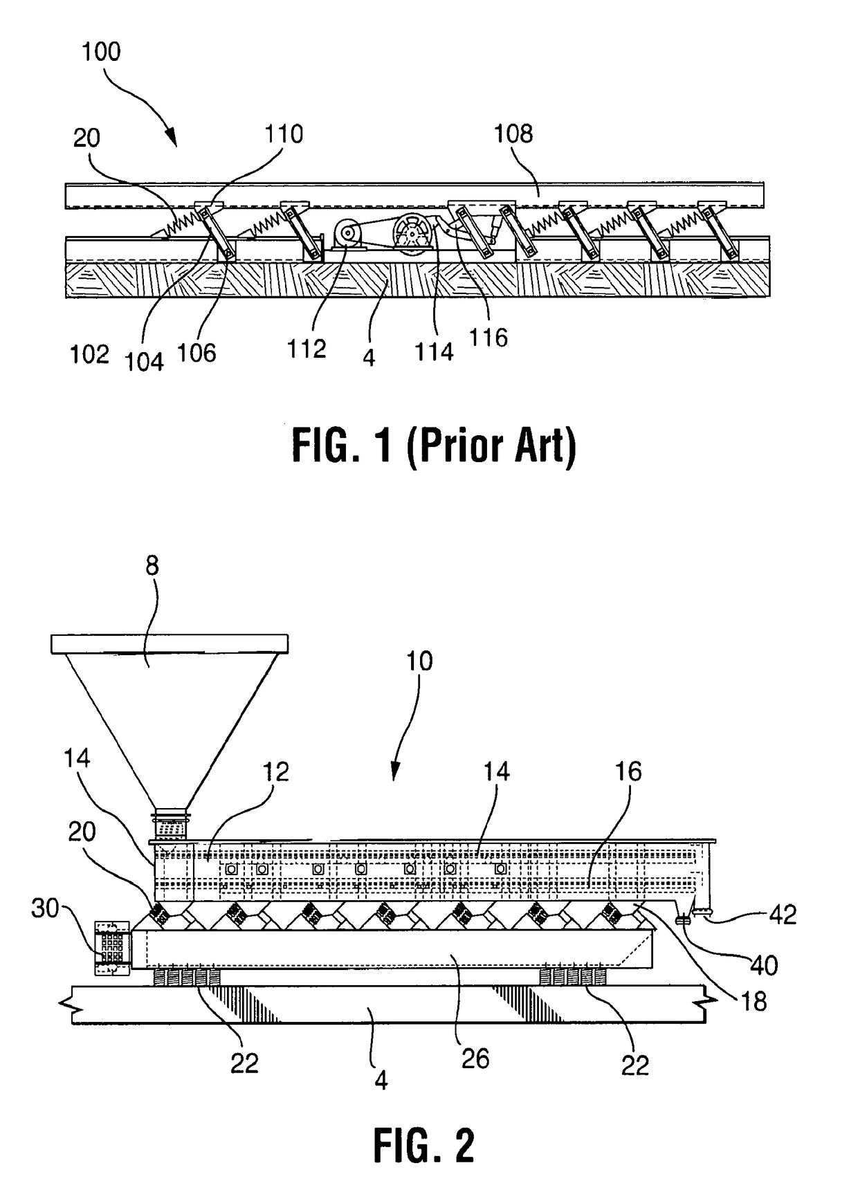
[0071]As shown in the FIGS. 1-17, a vibrating screening feeder system 1 includes a vibratory storage bin 8 feeding a vibrating screening feeder unit 10 feeding and crusher 70 for oversized material. The intermediate storage bin 8 is positioned above the vibrating screening feeder 10 connecting the bin outlet 102 to the feeder inlet interfacing chute 104. The size of the bin 8 is determined by the throughput to maintain a maximum feed rate to the vibratory screening feeder 10 and ensure an appropriate amount of storage to enable it to continuously operate at its rated TPH (ton per hour) capacity. The bin's outlet 102 is positioned close to the feeder inlet 103 separated by the feed plate 105. Preferably the bin 8 is a vibratory bin or hopper having the capability to shake accumulations or bridging particles from the sidewalls to effect a smooth flow of feed to the vibratory screening conveyor 10. The following U.S. patents are incorporated by reference herein are some of the vibrator...


PUM


Abstract

A vibrating screen feed conveying apparatus for conveying and separating sticky “moisture laden bulk solids” which are sticky and wet flowing onto a vibrating screening feeder and into a hopper. The apparatus includes a bed on which material is conveyed, a longitudinal counterbalance supported on a plurality of isolation springs, a plurality of inclined drive springs extending between the bed and the longitudinal counterbalance, and a plurality of stabilizers for controlling movement of the drive springs along their central axes. A plurality of vibratory motors, each having rotatable eccentric weights are attached to the rear end of the longitudinal counterbalance. The eccentric weights rotate in phase with one another to vibrate the bed at a vibration frequency.

Description

CROSS REFERENCES TO RELATED APPLICATIONS[0001]This application claims priority from PCT / US2016 / 000056 filed on Jul. 5, 2016 which claims priority from U.S. Provisional Application Ser. No. 62 / 493,460 filed on Jul. 2, 2016 and U.S. Ser. No. 62 / 231,330 filed on Jul. 3, 2015 all of which are incorporated by reference herein in their entirety.TECHNICAL FIELD[0002]The present invention relates to the field of industrial vibrating screens for separating small elements from large elements, such as in the case of coal or stone.BACKGROUND OF THE INVENTION[0003]In the handling of particulate bulk material, there are numerous ways for conveying such material and feeding it over an open end of the conveyor to a desired point of delivery. This invention is concerned with a conveyor or feeder vibrated as a free mass, i.e., the trough or conveyor is suitably isolated from the ground so that it may be vibrated in response to an oscillating force, as distinguished from a mass which is positively con...

Claims


Application Information

Patent Timeline
Patent Type & Authority Applications(United States)
IPC IPC(8): B07B1/44B65G27/32B65G27/20B65G27/04B65G27/26B65G27/30B07B1/42F23K1/00
CPCB07B1/44B65G27/32B65G27/20B65G27/04B65G27/26B65G27/30B07B1/42F23K1/00B65G2201/045B65G2201/047B07B2201/04B02C23/02B02C23/08F23H9/04B07B1/50B07B1/28
Inventor DUMBAUGH, GEORGE D.
Owner KINERGY
Why Eureka
Try Eureka