Inductors in beol with particulate magnetic cores

Active Publication Date: 2018-08-02
IBM CORP
View PDF10 Cites 2 Cited by
  • Summary
  • Abstract
  • Description
  • Claims
  • Application Information

AI Technical Summary

Benefits of technology

[0003]In accordance with embodiments of the present invention, an inductor device includes a conductive coil formed within a dielectric material and having a central core ar

Problems solved by technology

Inductor formation is often challenging in semiconductor fabrication.
Electroplated NiFe inductors have also been employed; however, these types of inductors suf

Method used


Image

  • Inductors in beol with particulate magnetic cores
  • Inductors in beol with particulate magnetic cores
  • Inductors in beol with particulate magnetic cores

Examples


Embodiment Construction

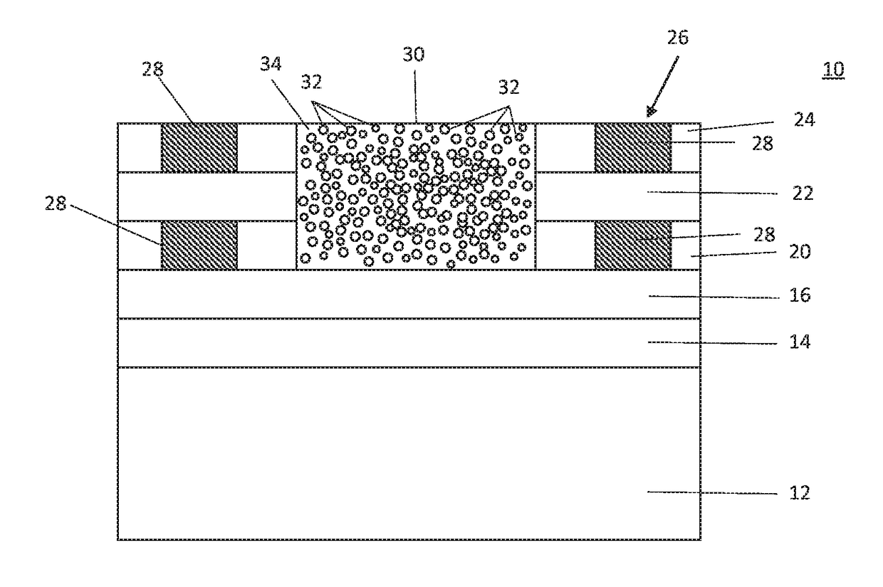
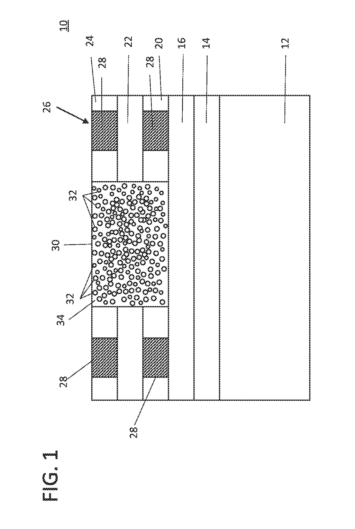
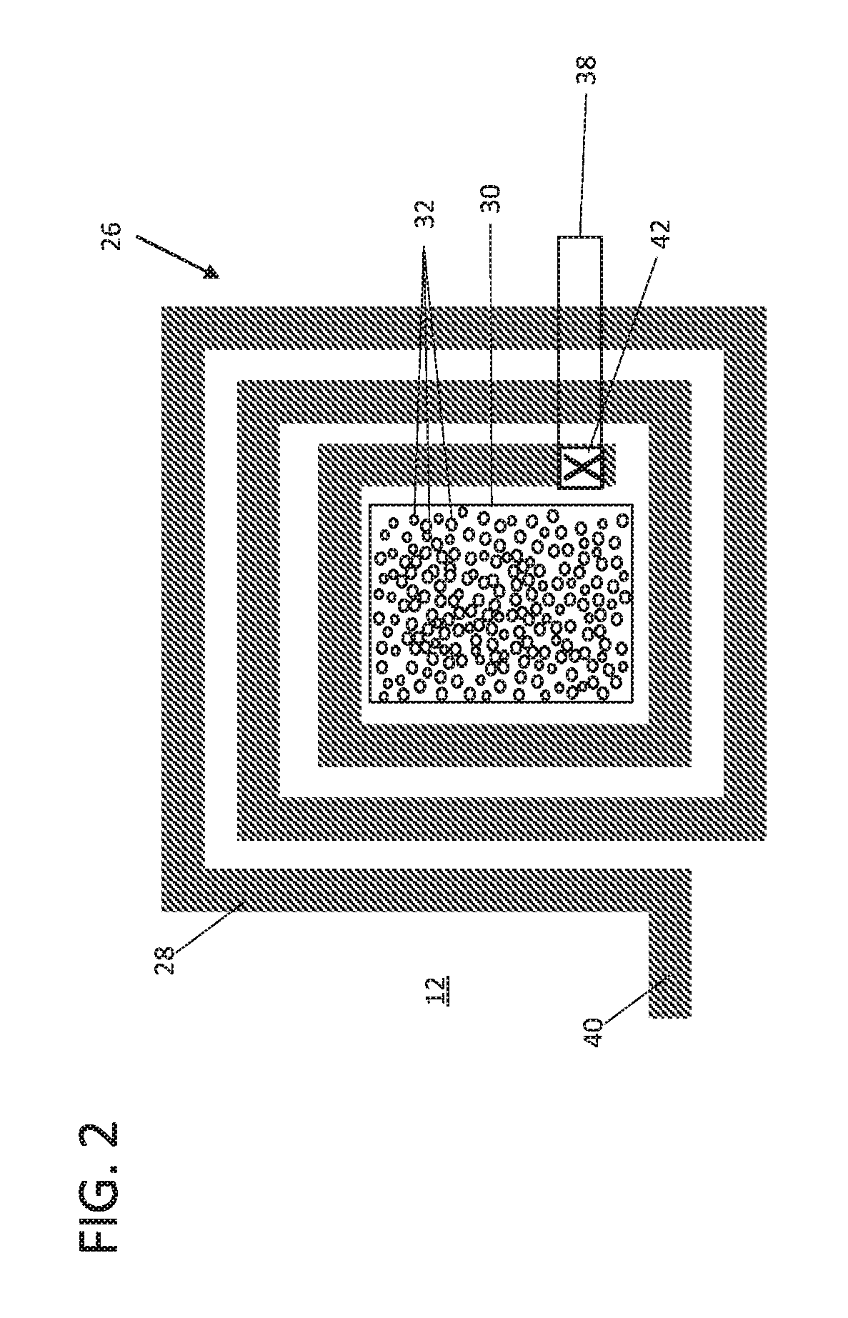
[0014]In accordance with aspects of the present invention, inductor devices are formed having a core formed using magnetic particles. After patterning the inductor device, which can be during, e.g., back end of the line (BEOL) processing, a deep trench is formed at a core of the inductor device. The core is filled with a matrix material having magnetic particles dispersed therein. Instead of sputtering, electroplating, etc. a solid magnet in the core, which leads to eddy current, a screen printing process can be employed to print fine particles of Co, Ni, Fe or alloys thereof covered with a suitable polymer matrix into the deep trench.

[0015]In useful embodiments, a distribution of particle sizes can be employed to achieve a high density of particles. In one embodiment, the particle density can preferably be at least 80% the density (e.g., volume density) of a bulk film of magnetic material. Note that hexagonal close packing of spheres having a same size has a packing factor of about...


PUM

PropertyMeasurementUnit
Percent by volumeaaaaaaaaaa
Densityaaaaaaaaaa
Currentaaaaaaaaaa

Abstract

An inductor device includes a conductive coil formed within a dielectric material and having a central core area within the coil. Particles are dispersed within the central core region to reduce eddy current loss and increase energy storage. The particles include magnetic properties.

Description

BACKGROUNDTechnical Field[0001]The present invention generally relates to inductive devices, and more particularly to inductive devices and methods for fabrication that include magnetic cores with magnetic particles.Description of the Related Art[0002]Inductor formation is often challenging in semiconductor fabrication. Inductors are usually formed with copper wires for radiofrequency applications and DC-DC power converter applications. Typically, air-core inductors are standard in the industry but have low values for energy storage. Also, on-chip power converters require a good Q-factor at high frequencies. Electroplated NiFe inductors have also been employed; however, these types of inductors suffer from loss due to eddy currents. While laminated structures and patterns can reduce the eddy current, current / charge confinement is limited by the patterning.SUMMARY[0003]In accordance with embodiments of the present invention, an inductor device includes a conductive coil formed within...

Claims


Application Information

Patent Timeline
IPC IPC(8): H01F27/255H01F41/02H01F27/29H01F41/04H01F27/28H01F27/34H01F27/32
CPCH01F2027/348H01F2027/2809H01F41/041H01F41/0206H01F27/255H01F27/327H01F27/29H01F27/2804H01F27/34H01F1/0054H01F1/09H01F3/08H01F5/00H01F27/02H01F41/028H01F41/042Y10T29/4902Y10T29/4906Y10T29/49073Y10T29/49075
Inventor KOTHANDARAMAN, CHANDRASEKHARANO'SULLIVAN, EUGENE J.WANG, NAIGANG
Owner IBM CORP
Why Eureka
Try Eureka