
Subsea equipment cleaning system and method

a technology of equipment cleaning and subsea, which is applied in the direction of membranes, well accessories, and treatment water sources, etc., can solve the problems of limited injection volume, limited space and weight on the platform or fpso, and high cost of topside, so as to achieve robust and cost-effective offshore topside

Active Publication Date: 2018-09-06
VETCO GRAY SCANDINAVIA
View PDF0 Cites 4 Cited by
  • Summary
  • Abstract
  • Description
  • Claims
  • Application Information

AI Technical Summary

Benefits of technology

The present invention improves current systems and methods for membrane operation, injection and production process equipment, and reservoir stimulation. It allows for a cost-effective and robust offshore topside and subsea hydrocarbon recovery process.

Problems solved by technology

The biggest challenges that offshore systems must overcome are the space and weight limitations on the platform or FPSO.
Injection volumes are limited by several factors and require valuable and costly topside space that should in an embodiment be used for production.
Sometimes the topside water treatment options are simply not feasible (e.g. existing brown oil fields without extra topside space, remotely located satellite oil fields, fields in harsh environments or in arctic conditions).
Deep subsea water treatment thus faces many challenges, including system mechanical design, electrification, control, inspection, fouling and scaling mitigation, maintenance and repair.
Designs and operations that are typically used for onshore and topside in most cases cannot be directly used under the deep subsea conditions.
One major problem in the operation of membrane filtration subsea is membrane fouling.
Scale problems can occur due to the incompatibility of the produced water with injected water or other sources of water, as is the case of the water present in drilling mud.
Electrodes in electrolyser cells (like electrochlorinators or similar equipment) are also subject to scale deposition and therefore may require acid for remediation.
However, the conventional CIP systems and operation methods face many challenges in offshore applications, both topside and subsea.
For deepwater membrane applications, subsea chemical storage needed for conventional CIP is most likely out of the question as the necessary chemical storage units are massive and costly.
If chemical storage units are on topside and the membrane systems are at the seabed, long and costly umbilicals will be needed to deliver and return CIP chemicals to / from subsea water treatment units, and may compromise projects in deeper waters and longer distance step-out wells.

Method used


Image

  • Subsea equipment cleaning system and method
  • Subsea equipment cleaning system and method
  • Subsea equipment cleaning system and method

Examples


Embodiment Construction

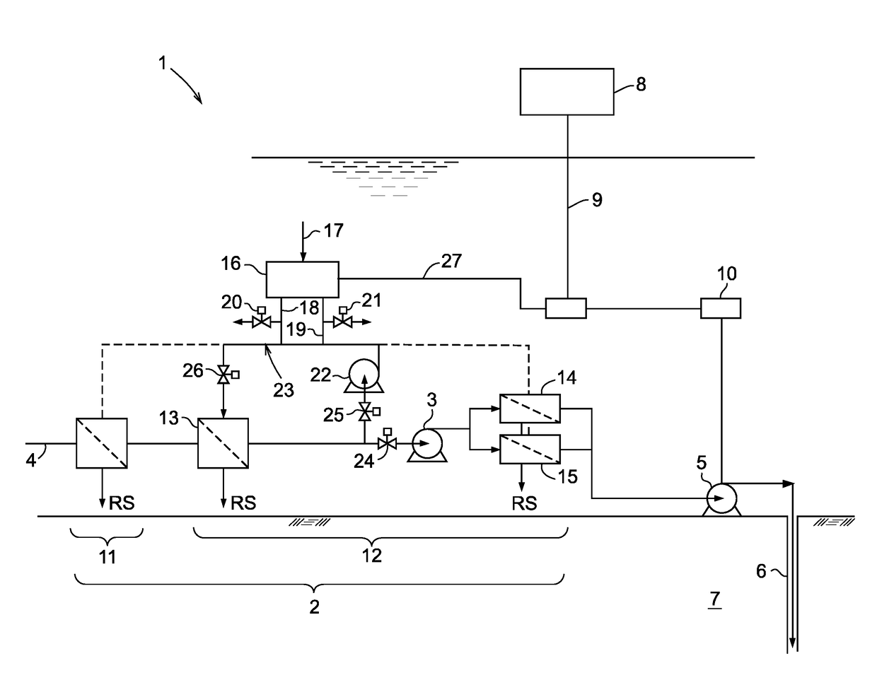
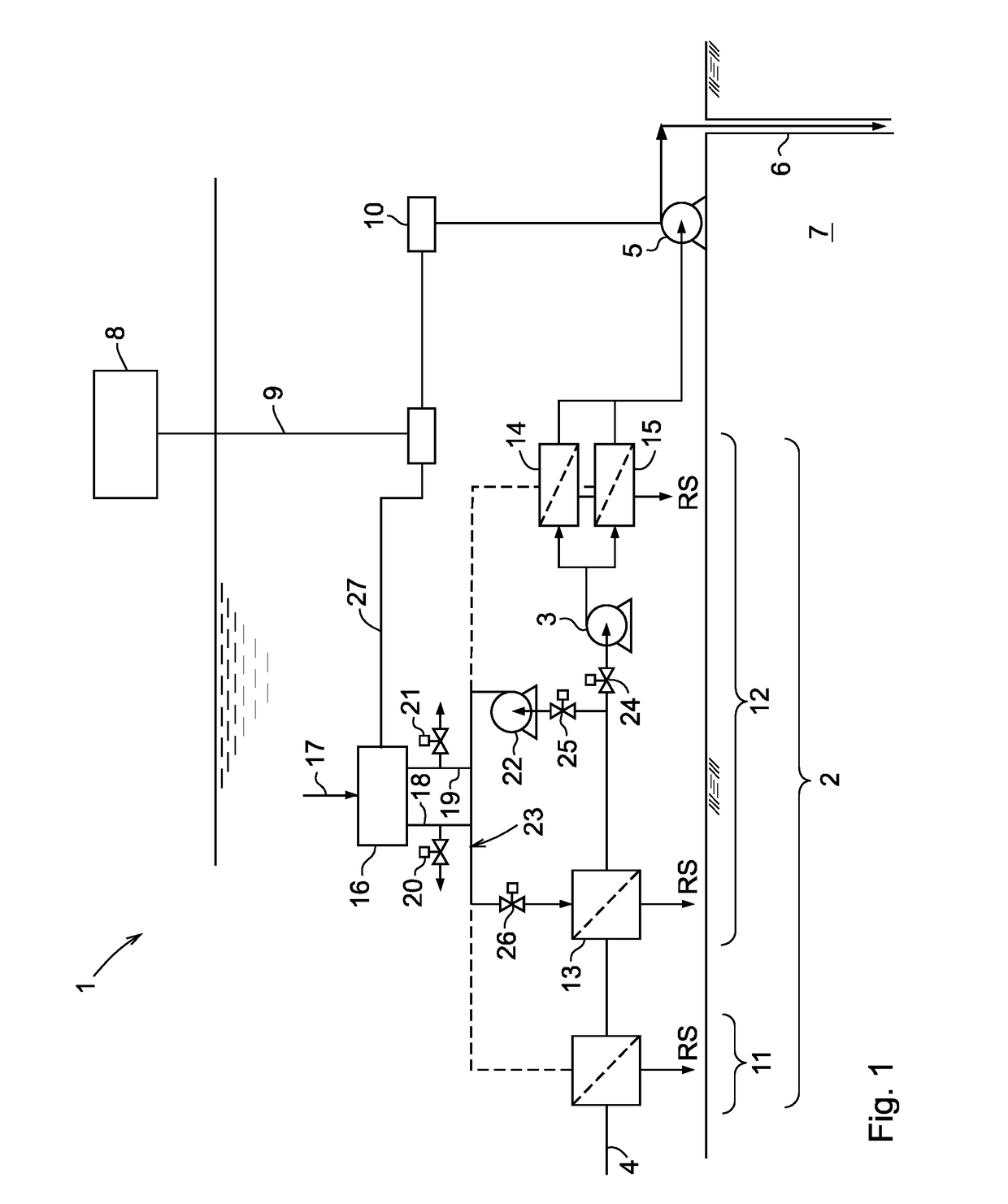
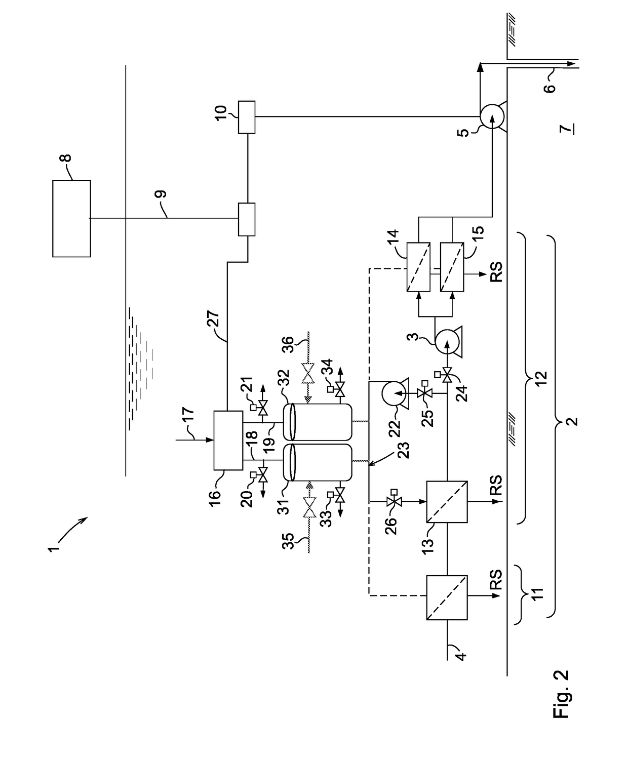
[0088]With reference to FIG. 1 an embodiment of the subsea water processing system in the form of a water injection system 1 briefly comprises a submerged water filtration station 2, a pump 3 feeding seawater or produced water through the filtration station from an inlet 4 to a water injection pump 5 by which treated water is injected into an injection well 6 in an oil and / or gas-holding subterranean formation 7. The water injection system 1 can be controlled from a topside control station 8 via an umbilical 9. A subsea control module 10 may be included in the control of the water injection system 1.

[0089]The submerged water filtration station 2 may comprise underwater membrane separation modules of successively finer grades as seen in the feed direction of water through the system 1. The filter stages may include a coarse filtration module 11 and a fine filtration module 12.

[0090]In this context separation of particulate matter and microorganisms from seawater typically involves fi...


PUM


Abstract

The invention concerns a subsea water processing system comprising an electrochemical unit that uses raw or treated seawater to generate high pH and low pH solutions that are used to clean at least one subsea process apparatus during a cleaning cycle by circulation through the at least one subsea process apparatus via acid or base flow lines connecting the electrochemical unit with the subsea process apparatus on-site.

Description

TECHNICAL FIELD OF THE INVENTION[0001]The present invention relates to subsea processing systems useful for processing of oil, gas, seawater (for injection), and produced water and methods for cleaning these subsea processing systems. Subsea processing systems include equipment for separation, pumping, gas compression, process cooling and heating, seawater injection and produced water treatment and re-injection into wells, and equipment for environmentally safe discharge of treated produced water. In particular, the invention relates to a subsea water processing system and a method for cleaning a subsea process apparatus included in the subsea water processing system.BACKGROUND OF THE INVENTION[0002]Water flooding is a widely used means for improved oil recovery (IOR) and has been used for more than 75 years. Water flooding is used to maintain or increase the reservoir pressure to extract the immobile oil present in the reservoir that would not otherwise naturally flow out of the re...

Claims


Application Information

Patent Timeline
IPC IPC(8): C02F1/46B01D61/02B01D61/42C02F1/461E21B37/08E21B43/36
CPCC02F1/4602B01D61/022B01D61/422C02F1/4618E21B37/08E21B43/36B01D2311/2623C02F2201/001E21B43/20B01D61/025B01D61/027B01D61/145B01D61/147B01D65/02C02F1/42C02F1/441C02F1/442C02F1/444C02F1/4693B01D2317/025B01D2321/162B01D2321/164C02F2001/46185C02F2001/4619C02F2103/023C02F2103/08C02F2103/10C02F2103/365C02F2201/46115C02F2301/08C02F2303/14C02F2303/20C02F2303/22E21B43/40B01D61/10B01D61/20B01D61/445B01D61/58B01D2311/04B01D61/026B01D2313/902B01D2313/903B01D2313/901B01D61/029
Inventor WANG, HUAXIA, ZIJUNPLASENCIA, JOSE LUIS
Owner VETCO GRAY SCANDINAVIA
Learn More