X-ray microscope

a microscope and x-ray technology, applied in the field of x-ray microscopes, can solve the problems of reducing the resolution and the field of view (fov), reducing the accuracy of shaping the wolter mirror at the order of 1 nm necessary for achieving a resolution at diffraction, and reducing the rear-side focal distance of an optical system. , to achieve the effect of increasing the use of x-ray microscopes, reducing the rear-side focal distan

Active Publication Date: 2018-09-13
OSAKA UNIV
View PDF2 Cites 33 Cited by
  • Summary
  • Abstract
  • Description
  • Claims
  • Application Information

AI Technical Summary

Benefits of technology

[0021]An X-ray microscope according to the present invention includes an X-ray source, a sample holding part, a concave KB mirror, a convex KB mirror, and a light receiving part located at a position in an imaging relation to the position of the sample holding part in this order along an optical axis, and thus can have a reduced rear-sid

Problems solved by technology

The high transmission power of an X-ray allows observation of a three-dimensional tomographic image of a thick sample, which is difficult with a transmissive electron microscope.
However, the Fresnel zone plate and the refraction lens are not suitable for multicolor imaging because of chromatic aberration occurring due to diffraction.
However, it is difficult to satisfy the Abbe sine condition with single reflection in an grazing-incidence optical system such as the KB mirror, and accordingly, coma occurs, which leads to decrease of the resolution and the field of view (FOV).
However, even when the state-of-

Method used


Image

  • X-ray microscope
  • X-ray microscope
  • X-ray microscope

Examples


embodiment 1

[0048]The following describes an X-ray microscope in Embodiment 1 of the present invention.

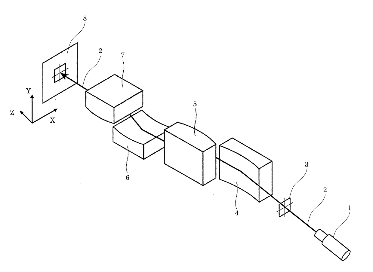
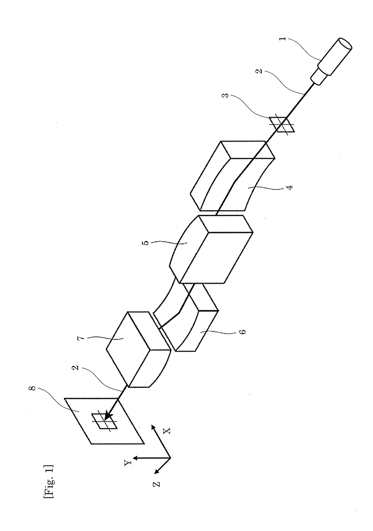
[0049]FIG. 1 is a perspective view of an optical system of an X-ray microscope in Embodiment 1. In FIG. 1, an X-ray 2 emitted from an X-ray source 1 as the origin of the X-ray optical system is incident on a sample holding part 3 holding a sample as a microscopic observation target. The X-ray 2 (including light emission and scattering light) having transmitted through the sample holding part 3 is reflected at, in the following order, the reflection concave surface of a concave KB mirror 4, the reflection convex surface of a convex KB mirror 5, the reflection concave surface of a concave KB mirror 6 having a normal orthogonal to the normal of the concave KB mirror 4, and the reflection convex surface of a convex KB mirror 7 having a normal orthogonal to the normal of the convex KB mirror 5. The X-ray 2 then arrives at a light receiving part 8 located at a position in an imaging relation to the ...

embodiment 2

[0055]FIG. 3 is a perspective view of the optical system of the X-ray microscope in Embodiment 2. The X-ray microscope in Embodiment 2 is different from the X-ray microscope in Embodiment 1 in that neither concave KB mirror 4 nor convex KB mirror 5 is provided in Embodiment 2. The other configuration is same as that of the X-ray microscope in Embodiment 1.

[0056]To evaluate an imaging characteristic of the X-ray microscope in Embodiment 2, a point spread function (PSF) that is distribution of an X-ray intensity at the light receiving part 8 is calculated under a condition that the X-ray source is an ideal point light source. FIG. 4 illustrates this point spread function. In FIG. 4, the horizontal axis represents a scale (centered at 500 nm) on the Y axis, and the vertical axis represents the X-ray intensity at the light receiving part 8. As illustrated in FIG. 4, a central peak has a half width (FWHM) of 38 nm, which indicates that a high space resolution is provided. Detailed condit...

embodiment 3

[0061]X-ray optical path simulation was performed, assuming an X-ray microscope in which the concave KB mirror 4 and the convex KB mirror 5 are not provided as in Embodiment 2. FIG. 5 illustrates an X-ray optical path up to a place separated by 120 mm from the sample holding part (zero point on the horizontal axis). The concave KB mirror 6 and the convex KB mirror 7 are disposed in this order halfway through the X-ray optical path.


PUM


Abstract

To provide an X-ray microscope that has a size small enough to be brought into a room by shortening the path length, an X-ray microscope including at least one of each of an X-ray source 1, a sample holding part 3, a concave KB mirror 4, a convex KB mirror 5, and a light receiving part 8 located at a position in an imaging relation to a position of the sample holding part 3 in this order along an optical axis is fabricated.

Description

TECHNICAL FIELD[0001]The present invention relates to an X-ray microscope, and particularly relates to an X-ray microscope using a Kirkpatrick-Baez mirror.BACKGROUND ART[0002]An X-ray microscope is an imaging optical system using electromagnetic wave having an extremely short wavelength, and has, in principle, a sub-nm high resolution significantly higher than that of an optical microscope. The high transmission power of an X-ray allows observation of a three-dimensional tomographic image of a thick sample, which is difficult with a transmissive electron microscope. In addition, basically, the X-ray microscope does not need vacuum formation, and thus, is suitable for observation in an environment (for example, an atmosphere of water solution and gas) in which in-situ measurement is required. In addition, not only electron density distribution but also a local coupling state and element distribution can be acquired by combining X-ray analysis technologies such as fluorescence X-ray a...

Claims


Application Information

Patent Timeline
IPC IPC(8): G21K7/00G21K1/06
CPCG21K7/00G21K1/065G21K1/067G21K2201/064G21K2207/00G21K1/06
Inventor MATSUYAMA, SATOSHIYAMADA, JUMPEI
Owner OSAKA UNIV
Why Eureka
Try Eureka