Method and device for detection of bioavailable drug concentration in a fluid sample

Active Publication Date: 2018-09-27
UNIV OF TENNESSEE RES FOUND +1
View PDF0 Cites 6 Cited by
  • Summary
  • Abstract
  • Description
  • Claims
  • Application Information

AI Technical Summary

Benefits of technology

The patent describes a method to detect the drug Propofol in low concentrations and accurately measure its signal using electrochemical techniques. The method is influenced by several factors, including pH and composition of the solution, voltage scan rate, and the deposition of biofilms / electrode fouling. The method allows for a rapid and reliable quantification of Propofol using microfabricated thin film microelectrodes and nanoelectrode arrays. The results can be used for the construction of an indwelling or ex vivo microfluidic sensor for closed-loop control systems that integrate into a TCIA biosensor for delivery of Propofol.

Problems solved by technology

A disadvantage of these known methods is that the pharmacokinetic model is a three-compartment model fitted to experimental plasma data.
With such a “black-box” method, there is no opportunity for the patient's individual drug-response to be considered.

Method used


Image

  • Method and device for detection of bioavailable drug concentration in a fluid sample
  • Method and device for detection of bioavailable drug concentration in a fluid sample
  • Method and device for detection of bioavailable drug concentration in a fluid sample

Examples


example 1

trode Design and Use for Propofol Detection

[0250]2,6-Diisopropylphenol (Propofol, DIPP) was purchased from Aldrich (D126608, St. Louis, Mo.) and used as received for preparation of stock solution 0.01M in 0.1 M NaOH or 0.1M in 3:7 mixture of water to methanol. All other aqueous solutions were prepared with Milli-Q Gradient A10 purified water.

[0251]Voltammetric measurements were performed using the Autolab / PGSTAT12 system equipped with the GPES Version 4.8 (Eco Chemie, Urtrecht, NL) in a standard three-electrode cell setup, i.e., with the platinum (2 mm diam.) or glassy carbon (BAS, 3 mm d.) disks macroelectrodes serving as working electrodes and the double junction (with 10% KNO3) Ag / AgCl Model 90-02 (Orion Research, Beverly, Mass.) and Pt-wire as reference and counter electrodes, respectively. Working macroelectrodes were always polished (using 0.3 μm particle size alumina) prior to use. The carbon microelectrodes were manufactured by standard lithography methods (Guillorn et al., ...

example 2

trode Design and Use for Propofol Detection

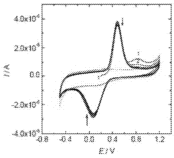
[0264]To develop a simple and faster “in-line” analytical technique for small sample volumes, the glassy carbon macroelectrode of Example 1 was replaced by a carbon microelectrode having the structure illustrated in FIG. 24.

[0265]The carbon microelectrode was prepared by the Oak Ridge National Laboratory using microfabrication technologies as previously described in the literature, (Guillorn et al., “Individually Addressable Vertically Aligned Carbon Nanofiber-based Electrochemical Probes,”J. Appl. Phys. 91: 3824 (2002); McKnight et al., “Effects of Microfabrication Processing on the Electrochemistry of Carbon Nanofiber Electrodes,”J Phys Chem B 107(39):10722-10728 (2003), each of which is hereby incorporated by reference in its entirety).

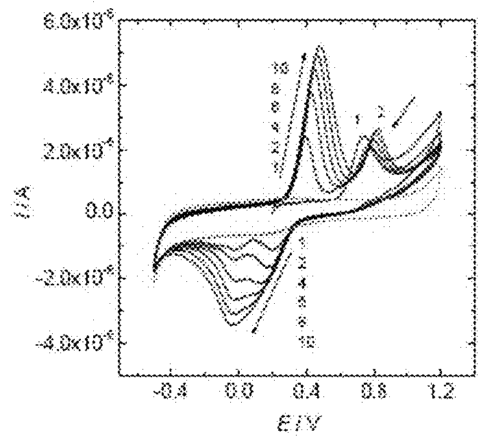
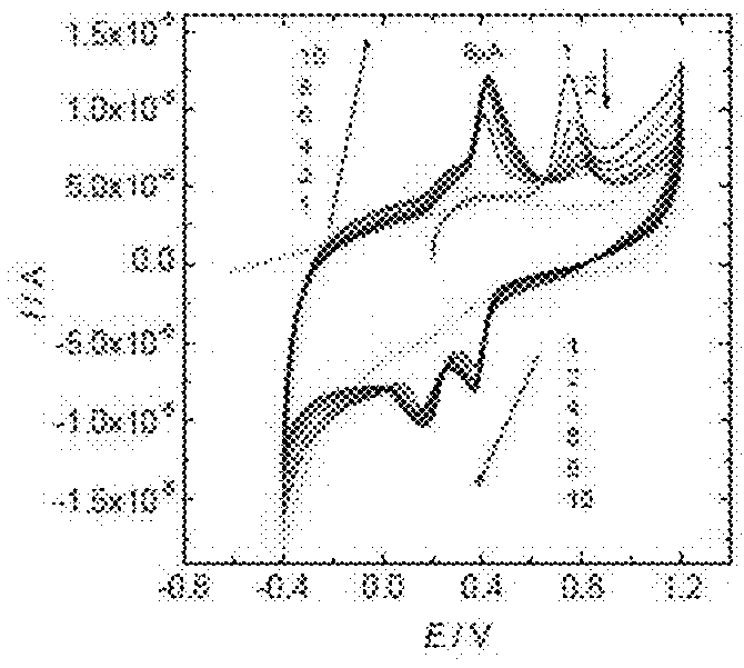
[0266]Having fabricated the carbon microelectrode, additional experiments were performed to the include a broad pH range (acidic, neutral, and basic solutions). These results are illustrated in FIG. 25. FI...

example 3

nofiber Sensor Array and Use for Propofol Detection

[0273]A prototype carbon nanofiber (CNF) array containing a chambered carbon nanofiber electrochemical sensor arrays with 40 individually addressable fibers was obtained from Oak Ridge National Laboratory. The array was prepared using known techniques (Guillorn et al., “Individually Addressable Vertically Aligned Carbon Nanofiber-based Electrochemical Probes,”J Appl. Phys. 91: 3824 (2002); McKnight et al., “Effects of Microfabrication Processing on the Electrochemistry of Carbon Nanofiber Electrodes,”J Phys Chem B 107(39):10722-10728 (2003), each of which is hereby incorporated by reference in its entirety). Each fiber in the array can be individually queried and the electrochemical signal assessed. The reproducibility and performance of selected fibers within the array was tested in ferrocene methanol solution. Signals obtained from selected CNFs were similar and summed appropriately when the currents were added together.

[0274]The ...


PUM


Abstract

The invention relates to a method for the controlled delivery of a drug as a function of bioavailable drug concentration, a sensor device for detecting bioavailable drug concentration, and a delivery device that controls delivery of the drug based on the real-time detection of bioavailable drug concentration.

Description

CROSS-REFERENCE TO RELATED APPLICATIONS[0001]This application is a continuation in part of U.S. application Ser. No. 15 / 611,089, which is a continuation in part application of U.S. application Ser. No. 13 / 124,036, which is a 371 National Stage Entry Application of International Patent Application No. PCT / US09 / 60852, filed Oct. 15, 2009, which claims the benefit of U.S. Provisional Patent Application No. 61 / 105,604, filed Oct. 15, 2008; and is a continuation in part of U.S. application Ser. No. 14 / 404,674, which is a 371 National Stage Entry Application of International Patent Application No. PCT / US2013 / 031747, filed Mar. 14, 2013, which claims the benefit of U.S. Provisional Patent Application No. 61 / 654,469, filed Jun. 1, 2012. All patents and patent application publications referred to in this application are incorporated herein by reference to the same extent as if set forth herein in their entirety.STATEMENT OF GOVERNMENT SPONSORSHIP[0002]The present invention was made with fund...

Claims


Application Information

Patent Timeline
IPC IPC(8): A61B5/1468A61B5/145A61B5/053
CPCA61B5/1468A61B5/14546A61B5/053A61B5/14539A61M25/0017A61B5/6852G01N27/403A61L2300/402A61M2205/3303A61B5/4839A61M31/002A61M5/14216A61M5/1452A61M5/172A61M2205/3576A61M2205/502A61M2205/52A61B5/1459G01N27/49G01N33/00
Inventor CHAUM, EDWARDLINDNER, ERNOGUO, JIDONG
Owner UNIV OF TENNESSEE RES FOUND
Why Eureka
Try Eureka