Filtration and reuse of surfactant-containing produced water for oil recovery

a technology of surfactant-containing produced water and oil recovery, which is applied in the direction of membrane technology, chemistry apparatus and processes, and wellbore/well accessories, etc., can solve the problems of increasing the cost and complexity of the process, and reducing the efficiency of the oil recovery process

Active Publication Date: 2018-10-18
DOW GLOBAL TECH LLC +1
View PDF4 Cites 1 Cited by
  • Summary
  • Abstract
  • Description
  • Claims
  • Application Information

AI Technical Summary

Benefits of technology

[0004]In a preferred embodiment, the membrane is treated with a surfactant that reduces membrane fouling due to oil present in the produced water and the same surfactant also improves the performance of treated water in the downhole injection bore by enhancing injectivity of the water in the oil bearing formation. The surfactant is selected both upon its ability to condition (i.e. “wet”) the membrane with water and to largely pass through the membrane to be present in the resulting permeate stream which is used for injection water for affecting an improvement in water flooding operation by improved injectivity of treated water and increasing recovery of oil from the oil bearing formation by making the formation more water wet. A variety of embodiments are described.

Problems solved by technology

The pretreated produced water may still contain small amounts of oil in addition to solids and salts that may adversely affect water flooding operations.
Unfortunately, the use of ceramic membranes for treating oil containing produced water adds to the cost and complexity of the process.
Polymeric membranes have limited utility in treating oil containing produced water, given their propensity to foul in the presence of oil.
Although chemical cleaning of polymeric membranes may be employed to remove the oil fouling of the membrane, such cleaning process may render the treatment process quite expensive due to high operating costs from periodic chemical treatment.

Method used


Image

  • Filtration and reuse of surfactant-containing produced water for oil recovery
  • Filtration and reuse of surfactant-containing produced water for oil recovery

Examples


Embodiment Construction

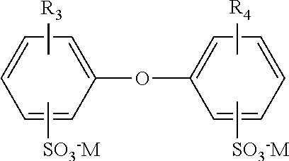
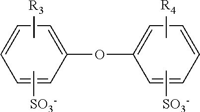
[0005]The membranes used in the present invention may be characterized as ultrafiltration membranes due to their preferred average pore size of from 0.01 to 0.1 μm. While the membranes may be fabricated into a variety of configurations, (e.g. flat sheet, hollow fiber, tubular, etc.), a hollow fiber configuration is preferred. The hollow fiber membranes are preferably assembled within a filter module including a tubular-shaped housing extended along an axis between an opposing first and second end with an inner chamber. The housing may be constructed from a wide variety of materials, e.g. plastics, ceramics, metals, etc., however, in one set of preferred embodiments the housing is made from an injection moldable plastic such as polyvinyl chloride (PVC) or acrylonitrile butadiene styrene (ABS). The module includes a plurality (e.g. hundreds) of semi-permeable hollow fiber membranes (“fibers”) located within the inner chamber. The fibers include a semi-permeable wall surrounding a lume...


PUM

PropertyMeasurementUnit
Mwaaaaaaaaaa
pore sizeaaaaaaaaaa
cloud pointaaaaaaaaaa

Abstract

A method for recovering oil from an oil bearing formation including the steps of: i) recovering an oil-water mixture from the oil-bearing formation; ii) separating at least a portion of the oil from the oil-water mixture to form a produced water; iii) adding a polymeric alkylene oxide surfactant having a Mw of less than 10000 Da to the produced water; iv) passing the produced water through a polymeric membrane to form a permeate stream and a retentate stream; and v) injecting the permeate stream into the oil bearing formation.

Description

FIELD[0001]The invention is directed toward oil and gas recovery methods involving the injection of an aqueous mixture including surfactants into an oil bearing formation for the purpose of improving oil recovery.INTRODUCTION[0002]Techniques for secondary and enhanced oil recovery such as water and chemical flooding involve the injection of an aqueous mixture down an injection well into oil bearing (e.g. subterranean reservoir) formation. The aqueous mixture often includes one or more of surfactants, scale-inhibitors, corrosion inhibitors, asphaltene inhibitors, viscosity agents, biocides, proppants, etc. See for example: U.S. Pat No. 3,945,437, U.S. Pat. No. 4,013,569, U.S. Pat. No. 4,532,051, U.S. Pat. No. 4,739,831, U.S. Pat. No. 5,013,462, U.S. 5,203,411, U.S. Pat. No. 6,581,687, US2011 / 0174485 and US2012 / 0101010. The producing wells produce the reservoir fluids that comprise hydrocarbons (oil and gas) along with the water from the formations. After the oil and gas is separated ...

Claims


Application Information

Patent Timeline
Patent Type & Authority Applications(United States)
IPC IPC(8): B01D69/12C09K8/584C02F1/44
CPCB01D69/125C09K8/584C02F1/444B01D69/10E21B43/38
Inventor MUKHERJEE, JOYDEEPDAS, SUPRIYOYU, WANGLINACEVEDO VELEZ, CLARIBELROZOWSKI, PETER M.FALCONE-POTTS, SUSAN K.
Owner DOW GLOBAL TECH LLC
Why Eureka
Try Eureka