Phase-tuning oscillators

a phase-tuning oscillator and phase-tuning technology, applied in the direction of oscillator generators, pulse generation by logic circuits, pulse techniques, etc., can solve the problems of phase noise degradation, circuit design and implementation of vcos suitable for direct lo signal synthetization, and the factor of tuning varactors is predominantly low, so as to achieve low power and simplicity. the effect of simplicity

Active Publication Date: 2018-12-06
CITY UNIVERSITY OF HONG KONG
View PDF0 Cites 9 Cited by
  • Summary
  • Abstract
  • Description
  • Claims
  • Application Information

AI Technical Summary

Benefits of technology

[0009]PT oscillators, including RPT oscillators, of the present invention may be utilized in various scenarios, such as certain direct-conversion architectures, communication systems utilizing phased arrays, etc., wherein multiple phases are desired. Accordingly, oscillators of embodiments of the invention may be configured to provide multi-phase output, such as to support direct-conversion architectures which are advantageous in terms of simplicity, image-free and low power, to enable phased-arrays employed for link budget improvement and beam-steering at mmW, etc. For example, multiple RPT oscillator cells may be cascaded together to provide stages of an N-stage LC-based RPT ring oscillator implementation. Each RPT oscillator cell may comprise a cross-coupled transistor pair and a differential transistor pair oscillator configuration providing oscillation frequency tuning in accordance with the concepts herein.

Problems solved by technology

However, circuit design and implementation of a VCO in CMOS suitable for such direct LO signal synthetization remains a major challenge, especially considering that a wide frequency range is typically required to tolerate process, voltage, and temperature (PVT) variations.
The quality factor of tuning varactors is predominantly low at mmW frequencies, which directly results in phase noise degradation.
Enlarging the VCO transistors and consuming more power could increase the oscillation amplitude and thus improve the phase noise, although the corresponding increase in induced parasitic capacitance would in turn narrow down the tunable frequency range of the VCO.
Moreover, if multiple-phase output were to be provided, the situation would worsen due to the additional loading from the coupling devices.
However, such techniques continue to require low-Q varactors in the VCO to continuously fine-tune the frequency.
Moreover, the phase noise at certain frequency ranges is poor, limiting the achievable figure-of-merit (FoM) for VCOs using these frequency tuning techniques.
If multi-phase oscillator were provided using these frequency tuning techniques, these techniques would inevitably experience performance degradation due to the more parasitics presented.

Method used


Image

  • Phase-tuning oscillators
  • Phase-tuning oscillators
  • Phase-tuning oscillators

Examples


Embodiment Construction

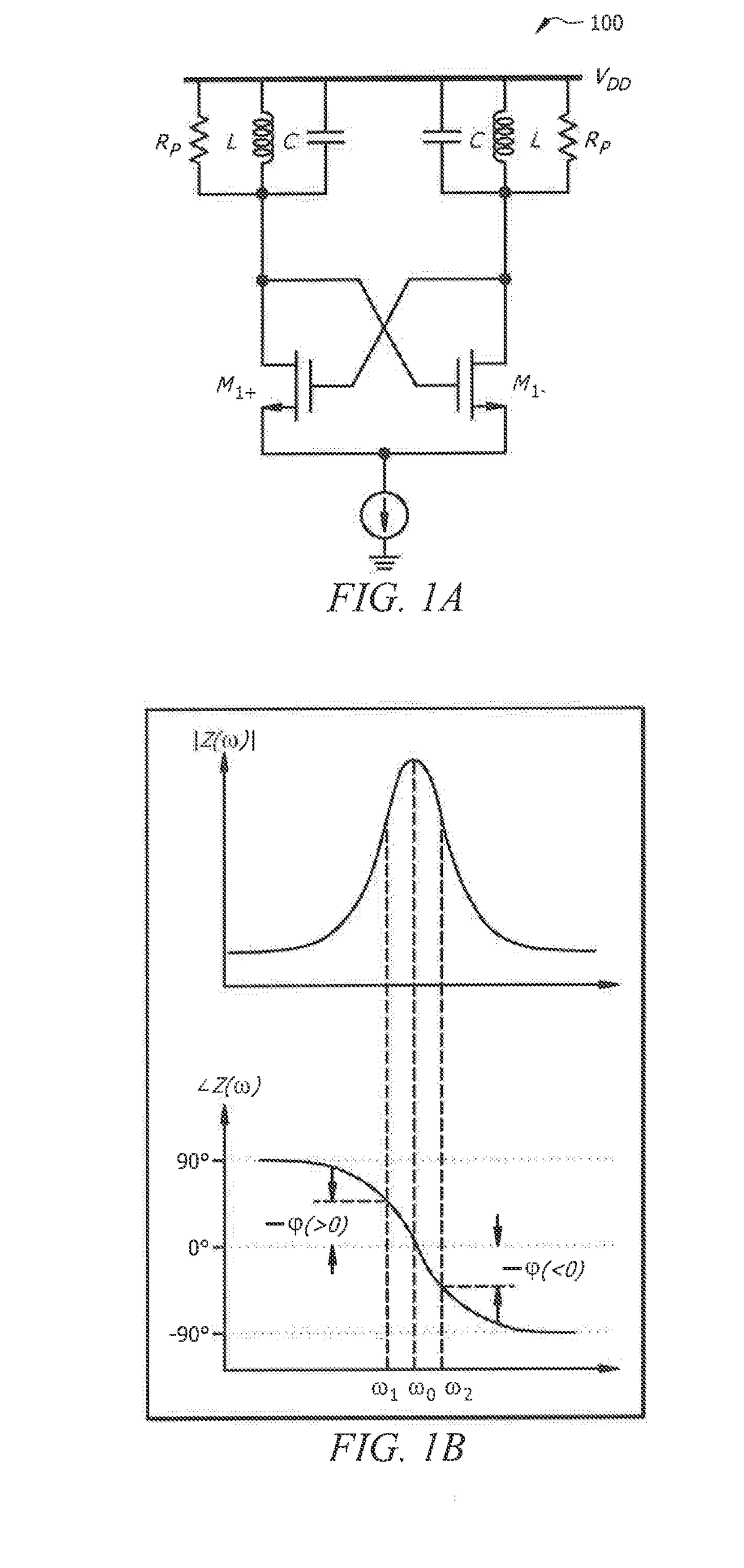
[0029]FIG. 1A shows a conventional differential inductance and capacitance (LC) based oscillator implementation as differential oscillator 100. It should be understood that stable oscillation of the differential LC oscillator of the illustrated example requires the negative transconductance of the cross-coupled transistor pair (M1+ and M1−) to be sufficient to compensate the tank loss represented by RP. In particular, this is the gain condition and an underlying phase condition is automatically satisfied when the oscillation frequency is derived. By treating the differential oscillator as a feedback loop composed of two single-ended inverting buffers, the phase condition that the total phase shift along the loop should be 360° becomes apparent. Since each of the cross-coupled transistors (M1+ and M1−) has a 180° phase difference between their output current and input voltage, the LC tank is required to contribute 00 phase shift, resulting in oscillation at the resonance frequency (i...


PUM


Abstract

Systems and methods which provide oscillator configurations implementing phase rotation (rotated-phase-tuning (RPT)) are described. Embodiments of a RPT oscillator may employ phase interpolation, whereby two current vectors having different phases are superimposed to provide a resultant current vector having a tunable phase to vary a phase shift in a feedback loop of an oscillator circuit and correspondingly tune the oscillation frequency. Phase rotation provided by an RPT oscillator configuration of embodiments inserts a negative phase shift (rotation phase shift) into each of two current branches to rotate the phase shifts of a phase-tuning technique, such as for avoiding phase ambiguity with respect to tunable oscillation frequencies. RPT oscillators of embodiments are varactor-less and are particularly well suited for operation to provide output frequencies in the millimeter-wave (mmW) band.

Description

TECHNICAL FIELD[0001]The invention relates generally to oscillator circuits and, more particularly, to providing variable oscillation frequencies using phase-tuning techniques, including rotated-phase-tuning techniques.BACKGROUND OF THE INVENTION[0002]The use of radio frequency (RF) signals, such as for providing wireless communication of voice, images, and data, for use in imaging, to provide sensing, etc., is commonplace to the point of nearly becoming ubiquitous. Due to various reasons, such as the availability of relatively unused spectrum, radiation providing penetration of a wide variety of materials, etc., the use of RF signals at higher and higher frequencies has become of interest. For example, the RF frequencies in the millimeter-wave (mmW) band are gaining increasing interest, such as for use with respect to the ever-increasing demands for high-data-rate wireless communication, radar sensing and imaging, etc. Various configurations of mmW transceiver systems useful in one...

Claims


Application Information

Patent Timeline
Patent Type & Authority Applications(United States)
IPC IPC(8): H03B5/12H03B27/00H03K3/03
CPCH03B5/1212H03K3/0315H03B27/00H03B5/1228H03B5/1215H03B2200/0074
Inventor XUE, QUANWU, LIANG
Owner CITY UNIVERSITY OF HONG KONG
Why Eureka
Try Eureka