Low voltage drop cascaded synchronous bootstrap supply circuit

a supply circuit and low voltage drop technology, applied in the field of low voltage drop cascaded synchronous bootstrap supply circuits, can solve the problem of limiting the number of levels that can be supported, and achieve the effects of reducing forward voltage drop, reducing voltage drop of bootstrap capacitor voltage, and reducing voltage drop

Active Publication Date: 2019-01-24
EFFICIENT POWER CONVERSION CORP
View PDF1 Cites 25 Cited by
  • Summary
  • Abstract
  • Description
  • Claims
  • Application Information

AI Technical Summary

Benefits of technology

[0006]The present invention overcomes the above-noted deficiencies of the prior art by providing a cascaded synchronous bootstrap supply circuit with reduced voltage drop between the cascaded bootstrap capacitors by replacing the bootstrap diodes of prior art circuits with gallium nitride (GaN) transistors. GaN transistors have a much lower forward voltage drop than diodes, can be made to support higher voltages, and have no reverse recovery, thus providing a cascaded gate driver bootstrap supply circuit with a reduced drop in bootstrap capacitor voltage, which is particularly important as the number of levels increases.

Problems solved by technology

This drop in voltage in each subsequent stage limits the number of levels that can be supported.

Method used


Image

  • Low voltage drop cascaded synchronous bootstrap supply circuit
  • Low voltage drop cascaded synchronous bootstrap supply circuit
  • Low voltage drop cascaded synchronous bootstrap supply circuit

Examples


Embodiment Construction

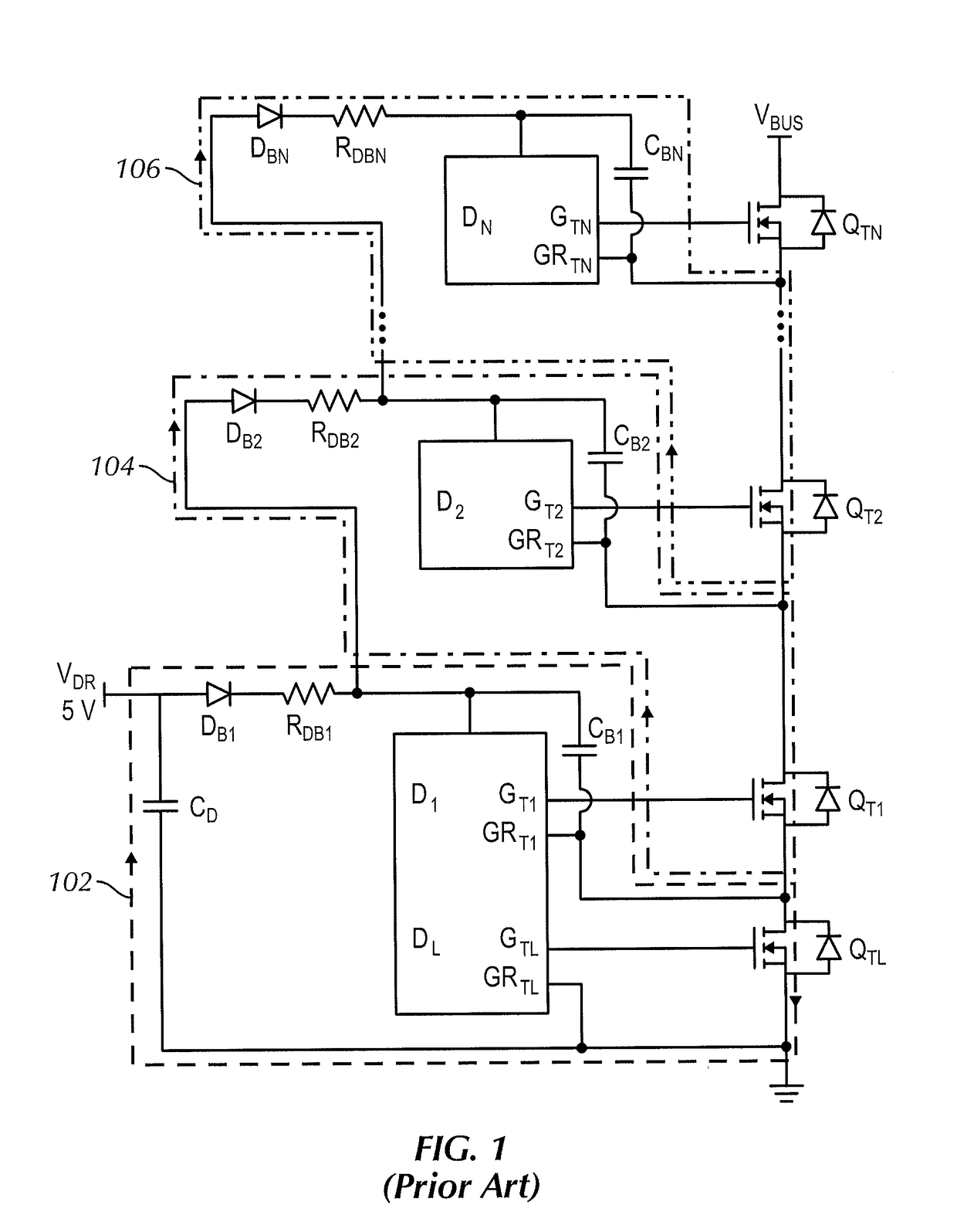
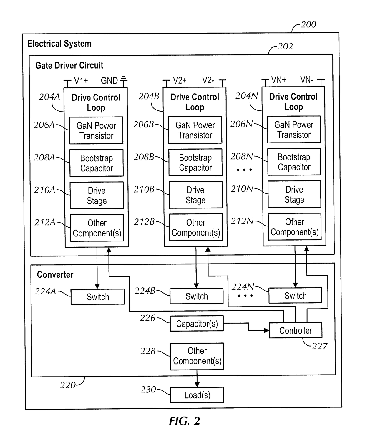
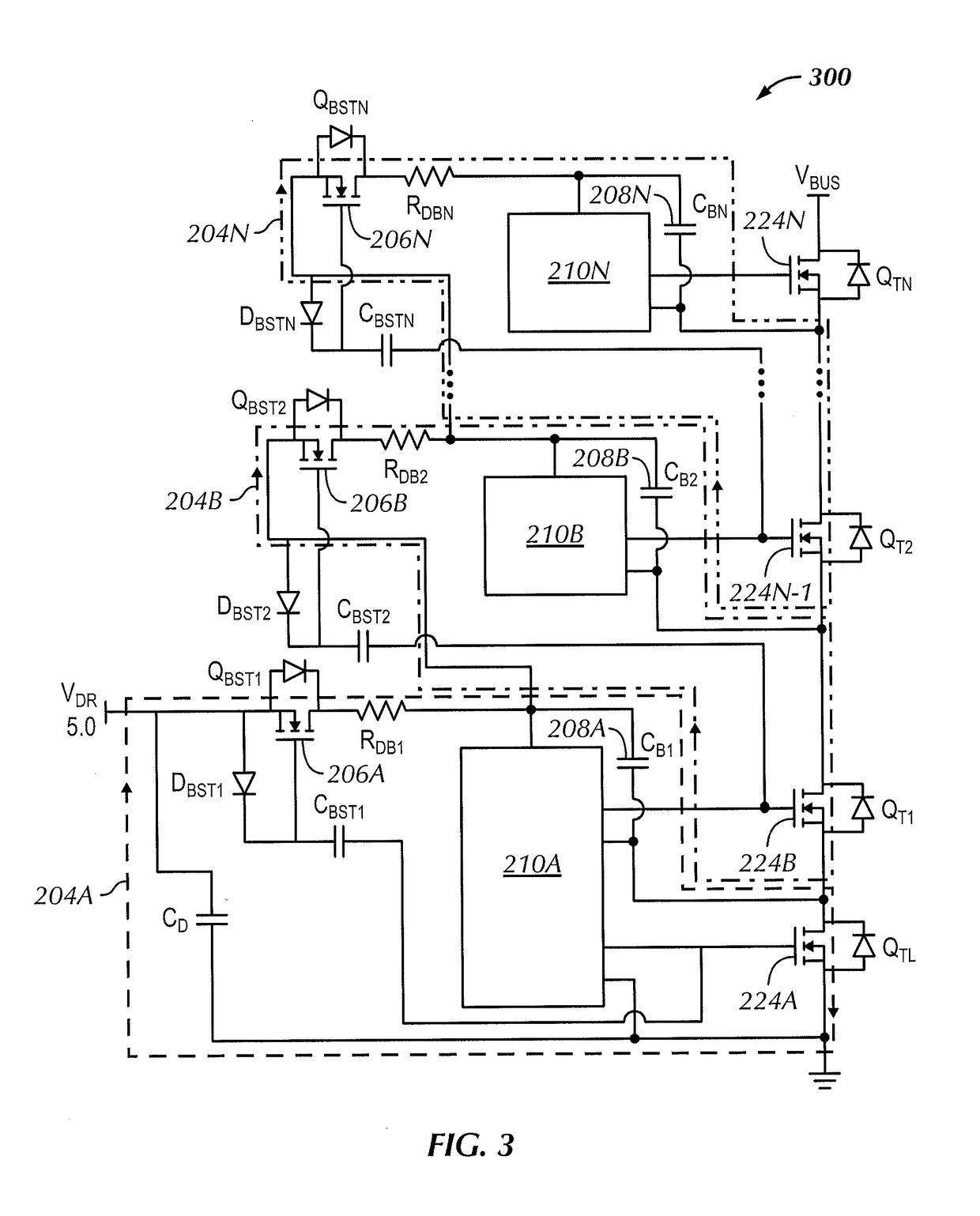
[0018]The present invention is directed to low voltage drop synchronous cascaded bootstrap supply circuits for multi-level DC-DC power converters. The circuit of the present invention comprises a plurality of cascaded gate driver control loops, each loop having a gallium nitride (GaN) transistor, a bootstrap capacitor, and a driver stage configured to selectively couple and decouple an adjacent control loop. In operation, each drive control loop is configured to selectively drive a separate power transistor (e.g., in a multi-level converter or switched-capacitor converter). More specifically, each drive control loop is configured to drive a separate power transistor in a sequence. In at least some embodiments, each drive stage comprises a controller, level shift logic, and complementary switches to follow the desired sequence.

[0019]In some embodiments, the GaN transistors used in the drive control loops are enhancement mode transistors. As used herein, “enhancement mode” transistors...


PUM


Abstract

A cascaded synchronous bootstrap supply circuit with reduced voltage drop between the cascaded bootstrap capacitors by replacing bootstrap diodes with gallium nitride (GaN) transistors. GaN transistors have a much lower forward voltage drop than diodes, thus providing a cascaded gate driver bootstrap supply circuit with a reduced drop in bootstrap capacitor voltage, which is particularly important as the number of levels increases.

Description

[0001]This application claims the benefit of U.S. Provisional Application No. 62 / 534,930, filed on Jul. 20, 2017, the entire contents of which are hereby incorporated by reference herein.BACKGROUND[0002]Power supplies and power converters are used in a variety of electronic systems. Electrical power is generally transmitted over long distances as an alternating current (AC) signal. The AC signal is divided and metered as desired for each business or home location, and is often converted to direct current (DC) for use with individual electronic devices or components. Modern electronic systems often employ devices or components designed to operate using different DC voltages.[0003]One type of power converter is referred to as a multi-level converter because more than two voltage levels are used to generate an output voltage. As a general rule, multi-level converters step-up to or step-down from a certain voltage using smaller discrete stages. There are numerous multi-level converter t...

Claims


Application Information

Patent Timeline
Patent Type & Authority Applications(United States)
IPC IPC(8): H03K17/06H02M1/088
CPCH03K17/063H02M1/088G05F1/46H02M3/00Y02B70/10
Inventor REUSCH, DAVID C.BISWAS, SUVANKARDE ROOIJ, MICHAEL A.
Owner EFFICIENT POWER CONVERSION CORP
Why Eureka
Try Eureka