Apparatus for vessel characterization

a technology of apparatus and stenosis, applied in the field of apparatus, system and method of stenosis of vessels and vessel modeling, can solve the problems of obstructed visual evaluation of the stenotic region, unable to accurately estimate the cross-sectional shape of the stenosis, etc., and achieve the effect of simple construction

Active Publication Date: 2019-02-14
KONINKLJIJKE PHILIPS NV
View PDF0 Cites 8 Cited by
  • Summary
  • Abstract
  • Description
  • Claims
  • Application Information

AI Technical Summary

Benefits of technology

[0013]In another aspect of the invention a system for characterizing a vessel of the living being is presented, the system comprising the apparatus according to the invention and the instrument configured for providing the first pressure measurement signal at the first measurement location and the second pressure measurement signal at the second measurement location within the vessel. In an embodiment, the instrument is configured to provide a third pressure measurement signal at a third measurement location. In an embodiment the instrument comprises a first, a second and a third pressure sensor for providing the first, second and third pressure measurement signals at the first, second and third measurement locations, respectively. In an alternative embodiment, the instrument comprises a single pressure measurement sensor, and the instrument is configured to provide the first, second and third pressure measurement signals by subsequent changes of a position of the pressure sensor along the vessel. The subsequent changes of position of the pressure sensor within the vessel may occur by advancing or retrieving (pullback) the instrument within the vessel, or a part of the instrument comprising the pressure sensor. The advantage of a single pressure sensor integrated into the instrument is a simpler construction, while the advantage of integrating multiple sensors into the instrument is that

Problems solved by technology

The weakness of the technique is that the cross-sectional shape of the stenosis can only be roughly estimated even by using multiple projections.
Furthermore, su

Method used


Image

  • Apparatus for vessel characterization
  • Apparatus for vessel characterization
  • Apparatus for vessel characterization

Examples


Embodiment Construction

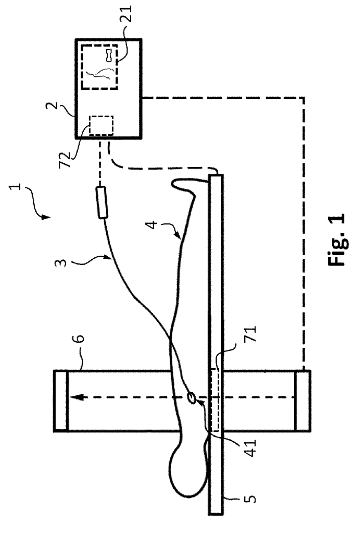
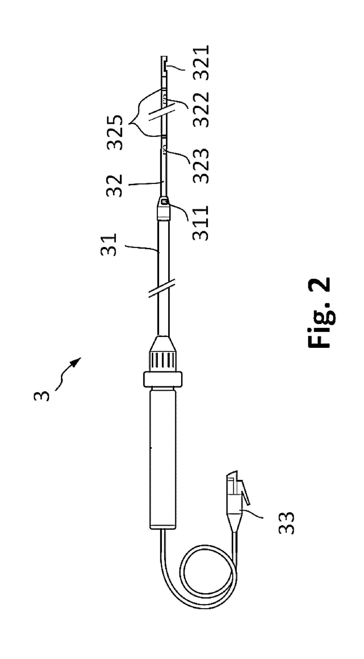
[0038]In FIG. 1 an embodiment of the system 1 for characterization of a vessel of a living being 4 is presented, wherein the living being may be a person or an animal. The system 1 comprises an apparatus 2 and an instrument 3, wherein the instrument is configured to provide pressure measurement signals from within a vessel of a portion 41 of the circulatory system of the patient 4, and the apparatus 2 is configured to ascertain characteristics of the vessel based on the pressure measurements. The apparatus 2 comprises a display 21 for rendering the characteristics of the vessel. Alternatively, the apparatus may be configured to provide signals to an external display on which the designated characteristics are presented to the physicians.

[0039]In an embodiment, the system comprises an imaging unit 6 for acquiring two-dimensional or three-dimensional morphological information of the vessel structure of interest upon injection of a contrast agent bolus into the targeted vasculature. Th...


PUM


Abstract

The invention discloses an apparatus (2), a system (1) and a method (100) for characterization of vessels and for vessel modeling. The cross sectional area (A1) of the vessel is derived from pressure measurements (p1, p2) obtained by an instrument (3) from within the vessel. When multiple cross sectional areas (A1, A2) are derived for multiple reference positions (r1, r2) based on pressure measurements (p1, p2, p3) along the vessel, a representation (20, 30) of the vessel can be rendered, without requiring any imaging modality. Furthermore, the effect of the pulsatile blood flow on the elasticity of the vessel walls can be visualized, supporting assessment of a stenosis or an aneurysm formation along the vessel.

Description

FIELD OF THE INVENTION[0001]The invention relates to an apparatus, system and method for characterization of vessels and for vessel modeling.BACKGROUND OF THE INVENTION[0002]A typical technique for identifying stenotic regions in a blood vessel is using angiography, whereas the functional impact of the stenosis is quantified with the fractional flow reserve (FFR) technique. FFR is calculated from the ratio of pressures at the distal and proximal ends of the stenosis, measured with a sensor positioned at the tip of a wire. The FFR value is a measure of the severity of the stenosis, and it can be established whether the stenosis limits blood flow within the vessel to an extent that treatment is required. Common treatment options include angioplasty, stenting or bypass.[0003]Angiography, a fluoroscopy imaging technique in conjunction with radio-opaque contrast agents, can be used to visualize the vasculature of a patient. Due to the nature of the technique, only the flow of the contras...

Claims


Application Information

Patent Timeline
IPC IPC(8): A61B5/02A61B5/00A61B5/0215A61B5/06G06T7/00
CPCA61B5/02007A61B5/02028A61B5/0035A61B5/0215A61B5/063G06T7/0012A61B5/1076A61B5/064A61B5/066A61B6/12A61B5/7425A61B5/02158A61B8/0841
Inventor HAASE, CHRISTIANGRASS, MICHAELSCHAEFER, DIRK
Owner KONINKLJIJKE PHILIPS NV
Why Eureka
Try Eureka