Time to digital converter with increased range and sensitivity

a time-to-digital converter and increased range technology, applied in the field of time-to-digital converter with increased range and sensitivity, can solve the problems of too large system handling and coarse estimate errors, and achieve the effect of optimizing analog/rf performance and high performan

Active Publication Date: 2019-02-21
INNOPHASE
View PDF0 Cites 7 Cited by
  • Summary
  • Abstract
  • Description
  • Claims
  • Application Information

AI Technical Summary

Benefits of technology

[0003]In one example embodiment, a TDC uses a combination of coarse and fine measurements to obtain a time measurement. In a further embodiment, the TDC is used within a demodulator of a low power receiver. In some applications, the receiver is a low power, high performance RF system on-chip (SoC) using nanometer technology that features a low, core supply voltage. Taking advantage of nanometer process technology, the receivers integrated...

Problems solved by technology

This coarse estimate may include an error amount due to the quantization size of the coarse measurement.
Each time a measurement is made, there is an error.
Embodimen...

Method used


Image

  • Time to digital converter with increased range and sensitivity
  • Time to digital converter with increased range and sensitivity
  • Time to digital converter with increased range and sensitivity

Examples


Embodiment Construction

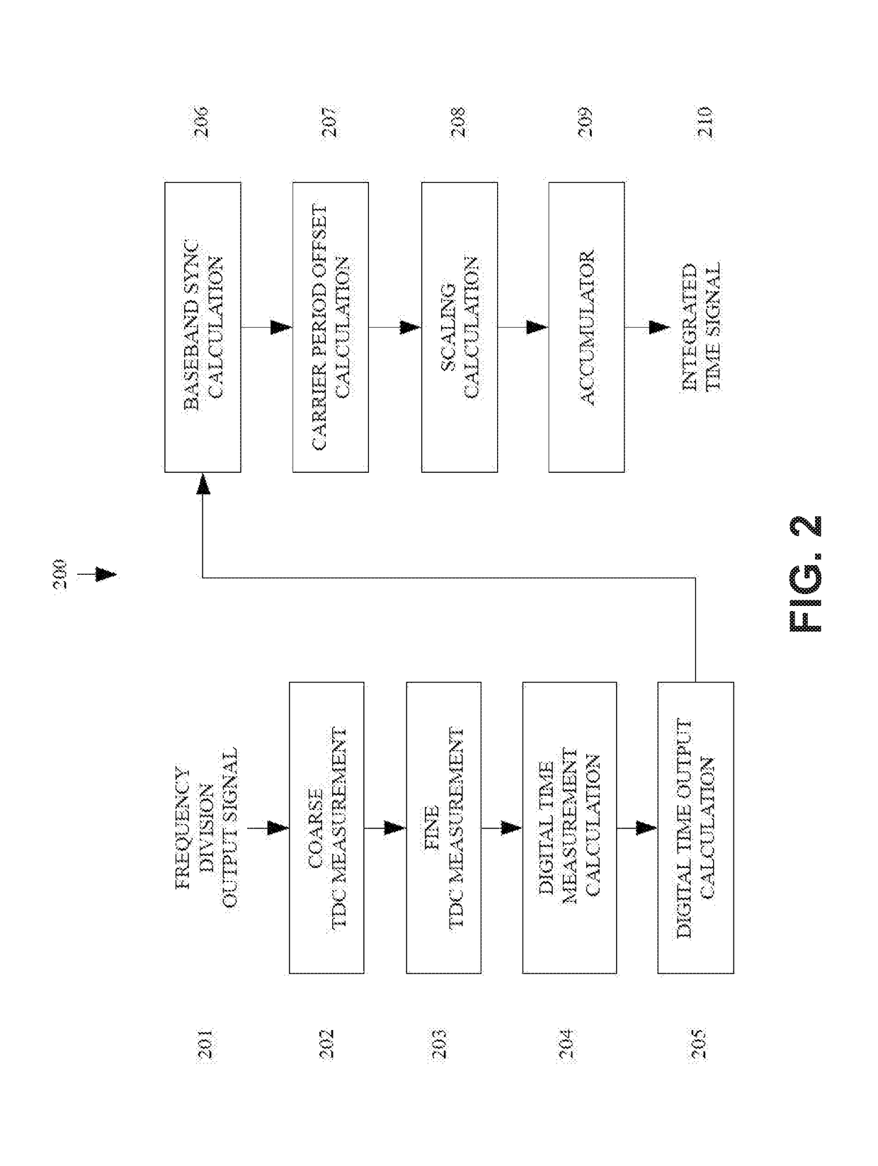
[0057]In one example embodiment, an Rx TDC covers a large range (several nanoseconds) with a small resolution (5×10⁻¹² seconds or 5 ps). Various embodiments use a sequence of coarse and fine time measurements to meet the range and resolution usage. Starting with a signal previously processed by other elements of a receive circuit (which will be labeled as the modulated signal), various circuits described herein make a coarse estimate of the period. The circuit makes a fine resolution estimate of the error. The system combines these coarse and fine measurements to arrive at an estimate of the input signal's period. Further processing occurs to convert the time measurement to a phase measurement.

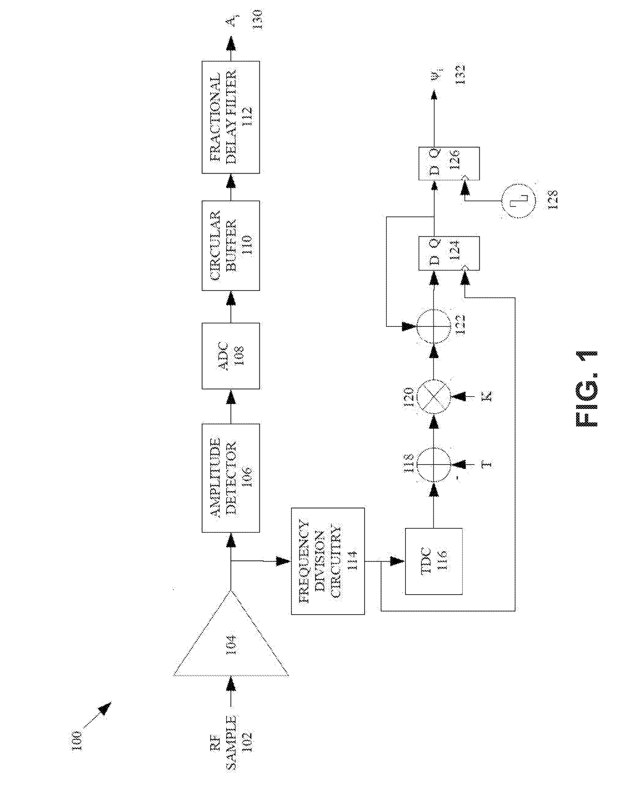
[0058]FIG. 1 is a block diagram of an example polar receiver. A radio frequency signal 102 is received by a polar receiver 100 and may be amplified by an amplifier 104. The polar receiver 100 operates to receive and decode modulated radio-frequency signals, such as signals modulated using phas...


PUM


Abstract

Systems and methods are described for determining a phase measurement difference between a received modulated signal and a local clock signal. An adjusted local clock phase measurement may be determined by subtracting, from the phase measurement difference, a phase correction that is based on the frequency difference between the modulator signal's carrier frequency and the local clock's frequency. A phase modulation value may be generated by scaling the adjusted local clock phase measurement. The scaling may be based on a ratio of the modulated signal's carrier frequency and the local clock's frequency. The phase correction may be based on (i) a count of periods of the modulated signal occurring between each corrected phase measurement and (ii) a difference between the carrier frequency and the local clock frequency.

Description

CROSS-REFERENCE TO RELATED APPLICATIONS[0001]This application is a continuation-in-part of U.S. application Ser. No. 15 / 488,278, filed Apr. 14, 2017, entitled “TIME TO DIGITAL CONVERTER WITH INCREASED RANGE AND SENSITIVITY,” which is hereby incorporated herein by reference in its entirety.BACKGROUND[0002]Time to Digital Converters (TDC) are generally used to provide a digital output representing a timing value. A typical TDC circuit measures a time difference between two events: a start and a stop event. In its simplest form, a counter updates based on a high frequency oscillator running at a frequency t0. The counter updates once every period(1f0).The TDC circuit initiates the counter when the start event occurs. The TDC reads the state of the counter when the stop event occurs and stores the value as the stop counter value. The count value, in conjunction with the counter update rate (or the period(1f0))may be used to determine the time difference between the start and stop events...

Claims


Application Information

Patent Timeline
IPC IPC(8): G04F10/00H04L27/227H03L7/091H03L7/099
CPCG04F10/005H04L27/2272H03L7/091H03L7/0992H03L7/0997G04F10/06
Inventor TESTI, NICOLO
Owner INNOPHASE
Why Eureka
Try Eureka