Wavelength conversion element, light source device, and projector

a technology of light source device and wavelength conversion element, which is applied in the direction of projectors, instruments, optics, etc., can solve the problems of limiting the increase of reflected fluorescence, unable to obtain sufficient scattering effect, and light loss of, for example, approximately 3 to 5%, so as to achieve the effect of improving fluorescence intensity

Active Publication Date: 2019-03-14
SEIKO EPSON CORP
View PDF0 Cites 4 Cited by
  • Summary
  • Abstract
  • Description
  • Claims
  • Application Information

AI Technical Summary

Benefits of technology

[0021]According to this configuration, the light source device with improved fluorescence intensity is used. Therefore, it is possible to realize the projector capable of obtaining a high-luminance projection image.

Problems solved by technology

In JP-A-2015-121586, it is described that when the average particle diameter of inorganic particles constituting the scattering layer is too small, it is difficult to obtain a sufficient scattering effect because of the wavelength dependence of Rayleigh scattering.
The reflective surface made of such metal is effective in terms of obtaining a high reflectance; however, the metal absorbs light, causing a light loss of, for example, approximately 3 to 5%.
Therefore, there is a limit to increasing the reflected fluorescence when the reflective surface made of silver or the like is simply used.

Method used


Image

  • Wavelength conversion element, light source device, and projector
  • Wavelength conversion element, light source device, and projector
  • Wavelength conversion element, light source device, and projector

Examples


first embodiment

[0032]Hereinafter, a first embodiment of the invention will be described with reference to FIGS. 1 to 5.

[0033]A projector according to the embodiment is one example of a liquid crystal projector including a light source device including a semiconductor laser and a wavelength conversion element.

[0034]In the drawings below, components may be shown in different dimension scales for the sake of clarity of each of the components.

[0035]The projector according to the embodiment is a projection-type image display device that displays a color video on a screen (projected surface). Three light modulators corresponding to color lights: red light, green light, and blue light are used in the projector. A semiconductor laser (laser diode) capable of obtaining high-luminance, high-output light is used as a light emitting element of a light source device in the projector.

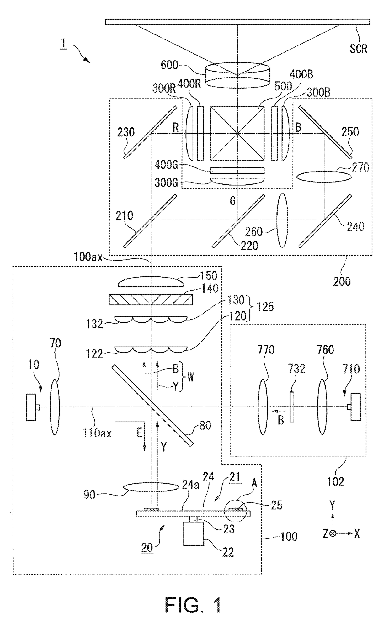
[0036]FIG. 1 is a schematic configuration diagram of the projector according to the embodiment.

[0037]As shown in FIG. 1, the proj...

second embodiment

[0106]Hereinafter, a second embodiment of the invention will be described with reference to FIG. 6.

[0107]Basic configurations of a projector and a light source device according to the second embodiment are similar to those of the first embodiment, and the configuration of a wavelength conversion element is different from that of the first embodiment. Therefore, an overall description of the projector and the light source device is omitted, and only the wavelength conversion element will be described.

[0108]FIG. 6 is a cross-sectional view of the wavelength conversion element 41 according to the second embodiment.

[0109]In FIG. 6, components common to those in the drawings used in the first embodiment are denoted by the same reference numerals and signs, and a detailed description of the components is omitted.

[0110]As shown in FIG. 6, the wavelength conversion element 41 includes the substrate 24, the reflective layer 26, a scattering layer 42, and the phosphor layer 25 (wavelength con...

third embodiment

[0118]Hereinafter, a third embodiment of the invention will be described with reference to FIG. 7.

[0119]Basic configurations of a projector and a light source device according to the third embodiment are similar to those of the first embodiment, and the configuration of a wavelength conversion element is different from that of the first embodiment. Therefore, an overall description of the projector and the light source device is omitted, and only the wavelength conversion element will be described.

[0120]FIG. 7 is a cross-sectional view of the wavelength conversion element 51 according to the third embodiment.

[0121]In FIG. 7, components common to those in the drawings used in the first embodiment are denoted by the same reference numerals and signs, and a detailed description of the components is omitted.

[0122]As shown in FIG. 7, the wavelength conversion element 51 includes the substrate 24, the reflective layer 26, a scattering layer 52, and the phosphor layer 25 (wavelength conver...


PUM


Abstract

A wavelength conversion element includes: a wavelength conversion layer including a first surface on which excitation light is incident, and a second surface opposed to the first surface; a scattering layer provided to face the second surface, containing a plurality of particles, and at least scattering fluorescence obtained by wavelength-converting the excitation light by the wavelength conversion layer; and a reflective layer provided to face the scattering layer and reflecting the excitation light or the fluorescence. The particle diameter of the particle is smaller than the wavelength of the fluorescence.

Description

BACKGROUND1. Technical Field[0001]The present invention relates to a wavelength conversion element, a light source device, and a projector.2. Related Art[0002]In a projector, a light source device capable of obtaining high-intensity emission light is demanded in order to realize a higher luminance of a projection image. In recent years, therefore, alight source device including an excitation light source and a wavelength conversion element has been proposed. In this light source device, fluorescence is generated by irradiating the wavelength conversion element with excitation light emitted from the excitation light source such as a semiconductor laser or a light emitting diode, and this fluorescence is used as a portion of illumination light.[0003]JP-A-2016-61853 discloses a wavelength conversion element including a substrate, an adhesive layer, a reflective layer, a scattering layer, and a phosphor layer. In JP-A-2016-61853, it is described, for example, that the scattering layer c...

Claims


Application Information

Patent Timeline
Patent Type & Authority Applications(United States)
IPC IPC(8): G03B21/20G02B26/00
CPCG03B21/204G02B26/008G03B21/2066G03B21/16G03B21/208G02B27/141G02B27/149G02B27/1046G02B27/0961
Inventor ITOH, YOSHITAKA
Owner SEIKO EPSON CORP
Why Eureka
Try Eureka