
Systems and methods for managing multi-layer communication networks

a multi-layer communication and network management technology, applied in data switching networks, digital transmission, hybrid transportation, etc., can solve the problems of affecting a large amount of users, the restoration path established by the optical layer may not meet the demands of the ip layer, and the latency of the optical layer is too high to be useful for the ip layer, so as to minimize the impact of communication through the network and restore communication failures

Active Publication Date: 2019-03-21
CISCO TECH INC
View PDF12 Cites 0 Cited by
  • Summary
  • Abstract
  • Description
  • Claims
  • Application Information

AI Technical Summary

Benefits of technology

The system enables rapid and efficient restoration of communication failures with reduced traffic outages during and after restoration, supports multi-vendor networks, and ensures service level agreements by optimizing restoration paths and constraints, thereby improving service continuity and reliability.

Problems solved by technology

Since such networks carry extremely large amounts of communication traffic, and are widely spread across multiple geographical locations, any connectivity failure at the IP or optical layers can impact a large amount of users.
A pure optical framework can rapidly restore optical routing, however, the restoration path established by the optical layer may not meet the demands of the IP layer—for example its latency could be too high to be useful for the IP layer.
In addition, optical restoration is only effective when the failure is in the optical domain and as such it does not take into account failures in the IP layer.
Finally, when the optical failure is repaired and the system reverts to normal mode (working path), the switch from the restoration path to the repaired working path without coordination with the IP layer may result in unnecessary traffic outages.
This requires provisioning of multiple “path options” to the router, which creates a cumbersome process and a rigid negotiation process between the layers, which follows a fixed order of increasingly relaxed constraints irrespective of the actual failure.
This is a time consuming process and creates churn since some restoration path, options can be irrelevant to the actual failure.
A distributed multi-layer framework poorly addresses multi-vendor networks, and multi-domain networks due to a lack of standards between vendors and networks.
Lack of central controller availability can result in severe traffic loss and service contract violation.
In addition, a centralized controller can experience signaling load and processing load during a large scale failure, causing slow recovery.
Due to these limitations, network operators are reluctant to adopt multi-layer framework solutions.

Method used


Image

  • Systems and methods for managing multi-layer communication networks
  • Systems and methods for managing multi-layer communication networks
  • Systems and methods for managing multi-layer communication networks

Examples


example 1

Network Restoration

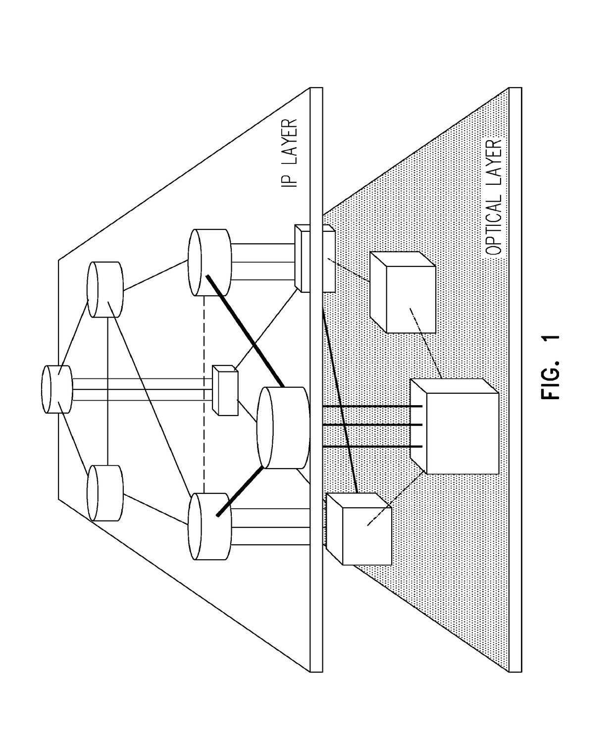
[0183]The network illustrated in FIG. 10 includes 4 IP routers 11-14, 4 ROADMs (optical routers) 21-24, 4 spare router ports connected to the optical layer 41-44, and 6 optical links 31-36.

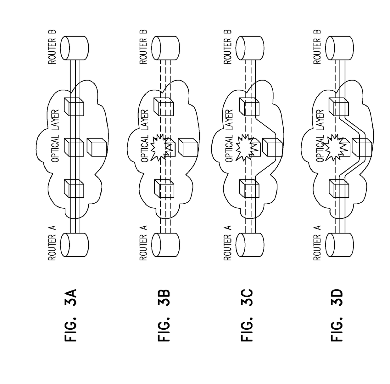
[0184]The length of optical links 31-34 is 10 km while link 35 is 50 km long and link 36 is 40 km long. Upon failure of link 31. IP links 51 and 52 fail. The shortest alternate optical path for these IP links goes through optical links 33, 32 and 34 (30 km). However, this path will force IP link 51 and 52 to share optical links with IP links 53-55, compromising the network in an event of another optical failure. Such a compromise may violate the IP layer policy of the service provider. The alternate path (33, 32, 34) is a likely choice for pure optical restoration since the optical layer is not aware of the diversity needs of the IP layer.

[0185]The present system will identify the path through optical links 35 and 34 as the better alternative since the resulting IP links will on...

example 2

Applying Traffic Engineering (TE) Metrics in Network Restoration

[0188]One approach for restoration described hereinabove assumes that the IP layer at restoration does not reroute traffic that is not suitable for the newly established restoration path.

[0189]In order to ensure that services with a low latency requirement retain the required latency while the network. is using longer optical paths when restoring some IP links, restoration of IP layer traffic can be effected along with modification of traffic engineering (TE) metrics, such as the latency of the link for the restoration path. This ensures that if latency of the restoration path of an IP link is too high, the routers will become aware of this change, and this link will not be used for latency-sensitive traffic. A similar approach can be used for the cost of the restoration path. If the cost increases due to routing through regenerators, or due to the increased length of restoration path, then the pertinent link metric mus...

example 3

Port-Matching via Traffic Count

[0192]Several approaches can be used to match client and server ports based an traffic counts through these ports. A group of N client and server ports is selected and samples are collected from these ports at fixed intervals. Two types of traffic counters can be used:[0193](i) Counters of the number of packets on the port; and / or[0194](ii) Counters of the number of bytes (octets) on the port.

[0195]The collected samples are pre-processed to verity that there is a sufficient number of samples for the algorithm. Gaps caused by missing samples are filled via, for example, interpolation. Sampling periods with decreasing samples values caused by, for example, manual reset of counters are ignored and byte counters for equipment that does not count some of the packet headers are adjusted accordingly. A “match value” that represents the likelihood of a match between every pair of ports, is then calculated according to one of the following approaches:[0196](i) ...


PUM


Abstract

A system for mapping a multilayer network having a server layer and a client layer is provided. The system includes a framework configured for comparing information obtained from a first traffic counter of a client port to information obtained from a second traffic counter of a server port to thereby determine if the client port and the server port are linked.

Description

FIELD AND BACKGROUND OF THE INVENTION[0001]The present invention relates to systems for managing multi-layer communication networks. Embodiments of the present invention relate to a framework for mapping interconnections between layers of the multi-layer communication network (cross-layer mapping) and managing communication failures in the multi-layer network.[0002]Decades ago, the rise in demand for telephony services spurred on the deployment of high capacity optical fiber networks. The subsequent rise in demand for Internet services resulted in leveraging of such optical networks for transmission of IP packets in an IP-over-Optical communication scheme. Such a multi-layer configuration utilizes the IP routers for controlling networking functions and the optical network for providing high throughput communication paths between the IP routers.[0003]FIG. 1 illustrates an example of a multi-layer network which includes an Internet Protocol (IP) layer connected over an optical layer (...

Claims


Application Information

Patent Timeline
Patent Type & Authority Applications(United States)
IPC IPC(8): H04B10/038H04L12/64H04L12/701H04L12/24H04L12/26H04Q11/00H04L12/703H04L45/28
CPCH04Q2011/0083H04Q2011/0073H04Q11/0066H04L45/28H04L12/6418H04L41/0668H04B10/038H04L45/00H04L43/0882H04Q2011/0081H04Q11/0071
Inventor SHIKHMANTER, YONAGERSTEL, ORNAN ALEXANDERAFRIAT, GALMILIAVSKY, VLADIMIR
Owner CISCO TECH INC
Features
  • Generate Ideas
  • Intellectual Property
  • Life Sciences
  • Materials
  • Tech Scout
  • Unparalleled Data Quality
  • Higher Quality Content
  • 60% Fewer Hallucinations
Learn More