Vascular Valved Prosthesis and Manufacturing Method

a vascular valve and prosthesis technology, applied in the field of fully biodegradable vascular valve prosthesis, can solve the problems of increasing the risk of infection, creating life-threatening conditions, severe disability of patients, etc., and achieve the effect of easy removal

Inactive Publication Date: 2019-04-04
ASSISTANCE PUBLIQUE HOPITAUX DE PARIS +2
View PDF0 Cites 5 Cited by
  • Summary
  • Abstract
  • Description
  • Claims
  • Application Information

AI Technical Summary

Benefits of technology

[0024]After electrospinning, the mandrel fixation (660, 760) means securing the shell pieces (640, 740) to the mandrel core (620, 720) may be loosened or removed, such that the shell pieces (640, 740) become detached from the mandrel core (620, 720). This allows removal of the mandrel core (620, 720) and / or fixation means, for instance by sliding out from within the surrounding shell pieces (640, 740), which during removal may remain in place. Once the core (620, 720) is removed the structural support for the shell pieces (640, 740) is lost so that they may collapse inwardly. When collapsing, the shell pieces (640, 740) do not form a firm contact with the surrounding electrospun conduit (200, 300, 400) and may therefore easily be removed out from the prosthesis without causing structural or frictional damage, and / or without the need for using solvents or the like.

Problems solved by technology

These diseases often result in malformations such as lesions found in the heart's valvar system or to the vascular system connected thereto.
Advanced stages may cause severe disability to the patient and even create life-threatening conditions through restriction or reduction of the blood flow to important organs.
Particularly, their implantation procedure carries increased risks of infection, stenosis and / or calcification of the tube giving rise to fibrosis, aneurysms, regurgitation and / or stenosis of the valve.
Further degeneration of the prosthetic solutions is then accompanied by a deterioration of the surgical corrections performed on the right ventricular outflow track, forcing the patient to redo the surgical procedure.
Therefore, because of their size and implications, these prostheses are considered very unsuitable for children.
Each of these numerous re-interventions then further increases the risk for diseases, such as haemorrhagic syndrome, stroke, coronary artery disease, arrhythmias, conduction issues, or hospital-acquired infections; thereby significantly contributing to increased mortality rates, particularly for children.
Another solution may be found by extracting biological valves from animals; however, these valves may be undesirable because of their degeneration with time, their limited supply and for ethical reasons.
However, achieving the inclusion of biocompatible materials within a product while also maintaining a high material and structural quality has proven difficult, in particular for complex tissue architectures.
For those sections a standard tubular vascular prosthesis becomes less reliable as it may be difficult, or even impossible, to connect all arterial branches with a single tube.
The medical choice may then be reconsidered to alternative shapes, such as bended prosthesis; however, these may result in a less reliable structural and material integrity over extended periods of time.
For these reasons, incorporating a sufficiently sturdy, yet still elastic enough splitting region into a vascular prosthesis and in particular a vascular valved prosthesis has proven difficult.
However, one difficulty faced by this technique is found in the removal of the product, i.e., the electrospun prosthesis, from the mandrel.
Hence, to remove it mechanical forces need to be applied which can damage the prosthesis and / or its components.
These deformations may degrade the structural and material integrity of the prosthesis prior to implant, thereby greatly diminishing the reliability and reproducibility of any prosthesis manufactured using electrospinning.
However, to remove this sacrificial layer, the prosthesis has to be placed in a solution that may negatively affect biological materials or even prematurely initiate biodegradation.
Alternatively, a sacrificial layer may be deposited consisting of materials with a lower electrical conductivity than the mandrel material, although, this in turn makes the electrospinning of a thick, i.e., above 100 μm, prosthesis very challenging and thus inaccurate.
However, this inadvertently leads to size variations of the prosthesis due to an unwanted excess space between the prosthesis and the mandrel, causing both the repeatability and reliability of the method to suffer.

Method used


Image

  • Vascular Valved Prosthesis and Manufacturing Method
  • Vascular Valved Prosthesis and Manufacturing Method
  • Vascular Valved Prosthesis and Manufacturing Method

Examples


example 1

s and Dimensions of an Electrospun Vascular Valved Prosthesis

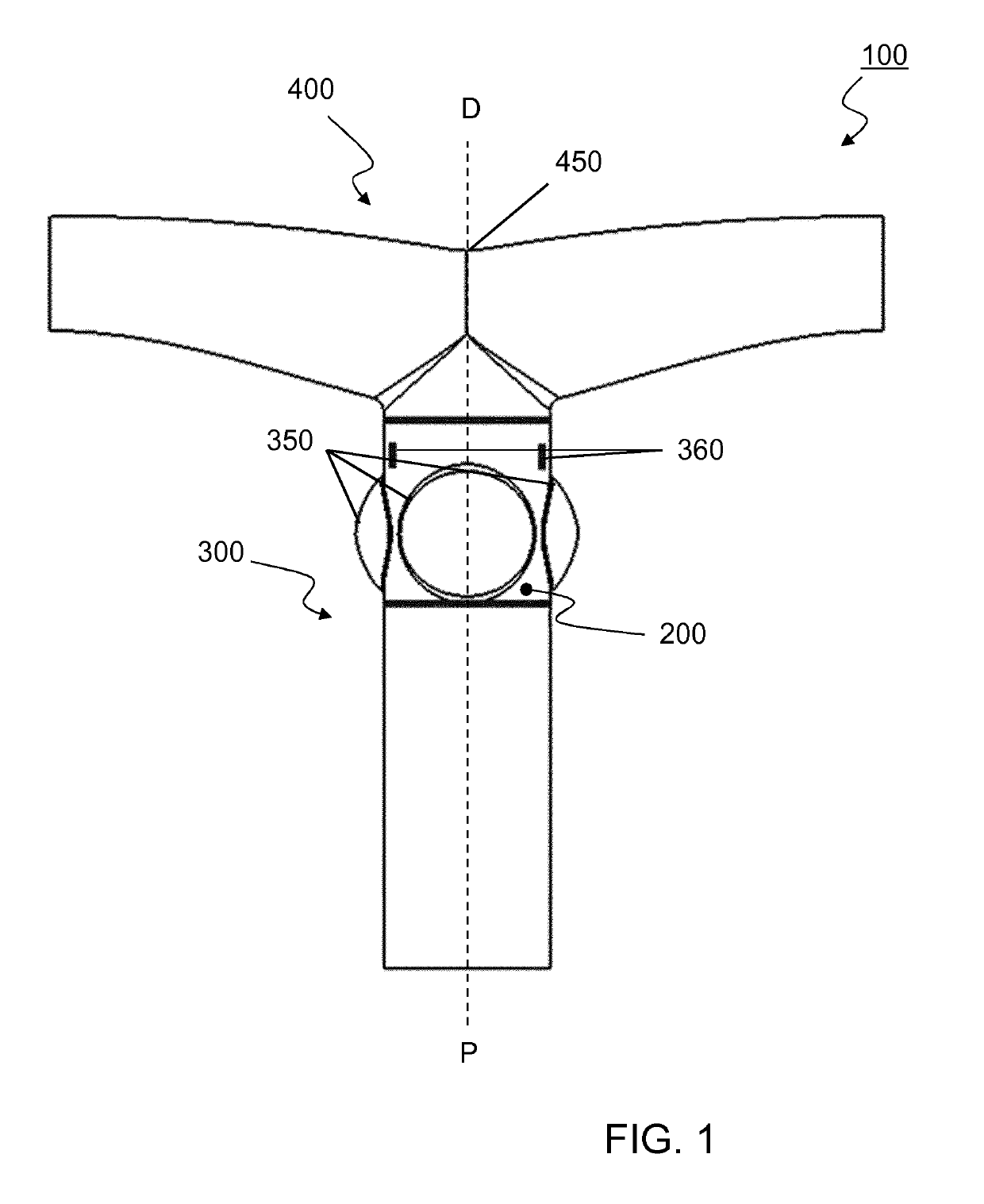
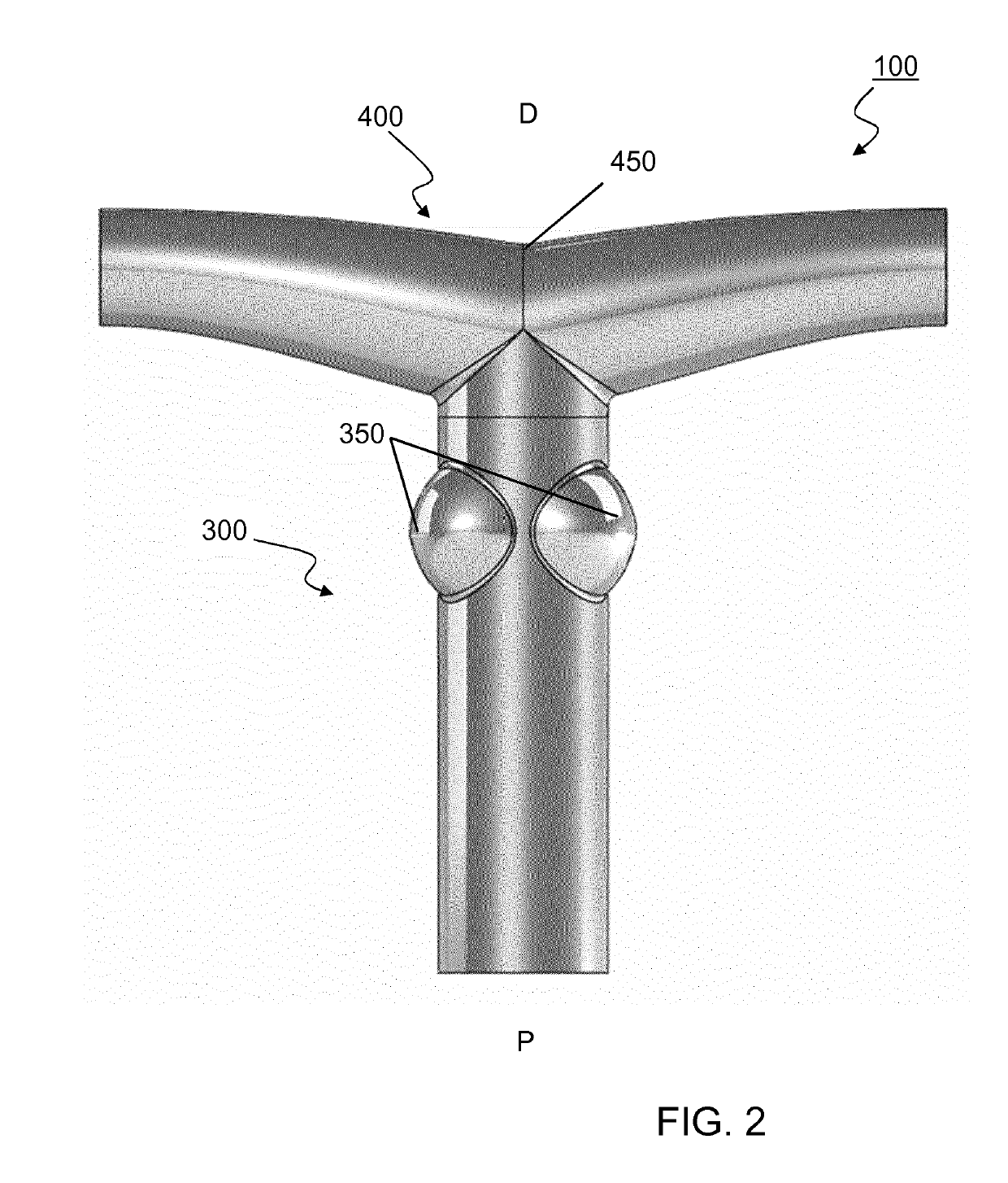
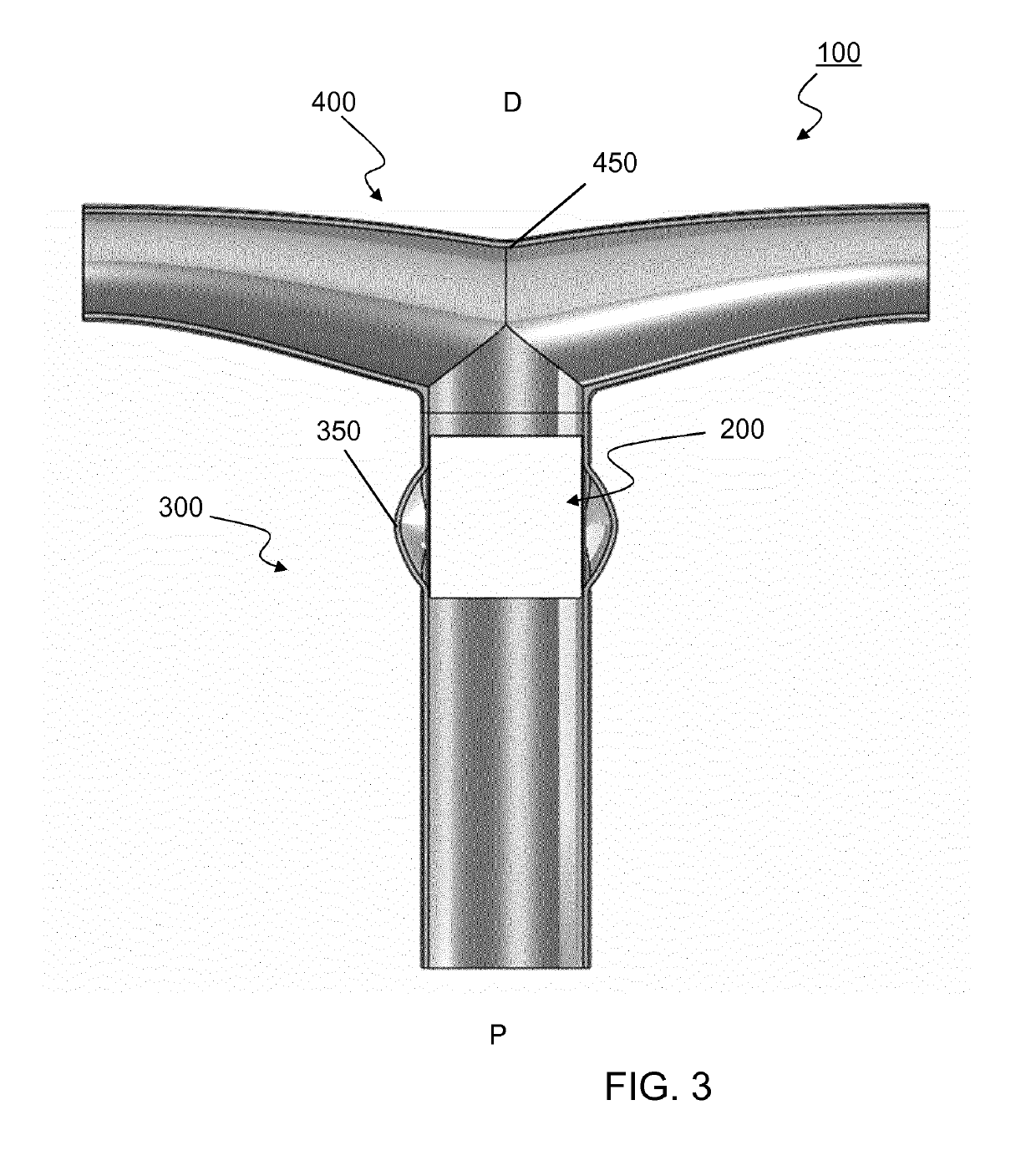
[0253]A vascular valved prosthesis as described in the present invention may be manufactured with different parameters and may thus be obtained in different dimensions. In an example, a T-shaped vascular valved prosthesis with a diameter of about 18 mm comprises an inner, outer and T-shaped conduit affixed together through an attachment. To better illustrate the example, a reference is made to FIGS. 11 and 12, which demonstrate a tubular vascular valved prosthesis from several perspectives; and FIGS. 13, 14 and 15, which similarly demonstrate a T-shaped vascular valved prosthesis.

[0254]The inner conduit of the T-shaped vascular valved prosthesis with a diameter of about 18 mm displays the following properties:[0255]The internal diameter of the inner conduit is 18 mm.[0256]The length of the inner conduit is 20 mm.[0257]The thickness of the inner conduit is between 0.05 and 0.3 mm, preferably around 0.1 mm.[0258]The linear e...

example 2

s and Dimensions of a Mandrel for Electrospinning a Vascular Prosthesis

[0296]FIGS. 6 and 17 demonstrate a mandrel (600) for electrospinning an outer conduit comprising the following dimensions:[0297]The cylindrical mandrel core (620) has a diameter of 14 mm.[0298]The cylindrical mandrel core (620) encapsulated by shell pieces has a diameter of 18 mm.[0299]The upper and lower fixation means (660), which are affixed to the cylindrical mandrel core (620) encapsulated by shell pieces (640), each have a diameter of 22 mm.[0300]The upper and lower fixation means (660) each have a length of 40 mm.[0301]The shell pieces (640) each have a length of 150 mm.[0302]The operable electrospinning distance on the shell pieces situated between the upper and lower fixation means (660) is 120 mm.[0303]The cylindrical mandrel core has a length of 295.5 mm.[0304]The upper and lower fixation means (660) have a length of 40 mm.[0305]The upper and lower fixation means (660) have a length of 40 mm.

[0306]Thes...

example 3

r the Manufactory of a Vascular Valved Prosthesis Comprising a T-Shaped Bifurcation Using a Mandrel for Electrospinning

[0308]As an example of a method for manufactory of a T-shaped vascular valved prosthesis (100) using a mandrel for electrospinning we refer to FIGS. 5-7 and 16-18. Respectively, FIGS. 5 and 16 demonstrate a schematic and an assembly of mandrel (600) for electrospinning the inner conduit (200); FIGS. 6 and 17 similarly demonstrate a mandrel (600) for electrospinning the outer conduit (300); and FIGS. 7 and 18 similarly demonstrate a mandrel (700) for electrospinning the T-shaped conduit (400).

[0309]The vascular valved prosthesis comprising a T-shaped bifurcation is manufactured by comprising the following steps:

(1) Solubilizing a polymer in an appropriate solvent for electrospinning, preferably 1,1,1,3,3,3-Hexafluoro-2-propanol preferably with a weight / volume concentration between 5-15% w / v.

(2) Electrospinning an inner conduit, an outer conduit and a T-shaped conduit...


PUM

PropertyMeasurementUnit
Young's modulusaaaaaaaaaa
diameteraaaaaaaaaa

Abstract

The present invention relates to an electrospun fully biodegradable vascular valved prosthesis, allowing tissue regeneration and growth potential optionally comprising a bifurcation, preferably T-shaped, a mandrel for electrospinning said vascular valved prosthesis, and a method for electrospinning said vascular valved prosthesis.

Description

FIELD OF THE INVENTION[0001]The present invention relates to a fully biodegradable vascular valved prosthesis, allowing tissue regeneration and growth potential, a mandrel for electrospinning said vascular valved prosthesis, and a method for electrospinning said vascular valved prosthesis.BACKGROUND TO THE INVENTION[0002]Vascular, valvar and cardiac diseases are characterized by an abnormal condition of the blood vessels or valves. These diseases often result in malformations such as lesions found in the heart's valvar system or to the vascular system connected thereto. Advanced stages may cause severe disability to the patient and even create life-threatening conditions through restriction or reduction of the blood flow to important organs. Treatment of the malformations usually involves a surgical correction to repair the right ventricular outflow track (RVOT), i.e. a major cardiac output channel which is involved in over half of congenital heart disease pathology. Examples of mal...

Claims


Application Information

Patent Timeline
Patent Type & Authority Applications(United States)
IPC IPC(8): A61F2/24
CPCA61F2210/0004A61F2240/002A61F2/2415A61F2230/006A61F2250/0082A61F2/2412
Inventor KALFA, DAVIDMENASCHE, PHILIPPEPOUPONNEAU, PIERRELEONARD, CLEMENTPERROT, SEBASTIEN
Owner ASSISTANCE PUBLIQUE HOPITAUX DE PARIS
Why Eureka
Try Eureka