Hotspot correction method

a hotspot correction and lithographic technology, applied in the field of lithographic hotspot correction methods, can solve the problems of requiring enormous calculation capability, affecting the accuracy of overlays and pattern coverage rates, and the right-angled pattern corner in the photomask layout will inevitably be subject to rounding distortion, so as to improve the distortion of target patterns, accurate correction, and accurate correction

Active Publication Date: 2019-04-04
SHANGHAI HUALI MICROELECTRONICS CORP
View PDF0 Cites 10 Cited by
  • Summary
  • Abstract
  • Description
  • Claims
  • Application Information

AI Technical Summary

Benefits of technology

[0027]According to the present invention, the target patterns within the hotspot regions are accurately corrected by using the ILT method. Furthermore, to improve the distortion of the target patterns within the extension regions due to ILT correction of the hotspot regions, the OPC method is employed thereafter to restore the target patterns within the extension regions. As a result, the target patterns within the hotspot regions can be accurately corrected and pattern distortion generated due to regional ILT correction can be prevented. Moreover, high demanding of calculation capability and long calculation time of global ILT correction can be avoided.

Problems solved by technology

However, during the lithographic process, due to the resolution limitation of optical imaging, the right-angled pattern corner in the photomask layout will be inevitably subjected to rounding distortion when exposed and imagined on a silicon wafer.
If not being corrected properly, such corner distortion will cause various problems like size reduction of the pattern corner, which will bring adverse effects on the overlay accuracy and the pattern coverage rate.
More seriously, such rounding distortion may also convert patterns which conform the design rules and designed to be safe in the layout into hotspots with insufficient process window.
However, the size of the segments and the design of the assist patterns mainly depend on experience, which may easily cause hotspots due to the improper segmentation and assist patterns.
Although the PXOPC has the above advantages, the movement and simulation of the curvy contour of the photomask pattern demands enormous calculation capability.
For example, the calculation time is four times greater than that of the conventional OPC method with the same number of CPUs, thus global correction cannot be performed.

Method used


Image

  • Hotspot correction method
  • Hotspot correction method
  • Hotspot correction method

Examples


Embodiment Construction

[0033]The invention will be described in further details hereinafter with respect to the embodiments and the accompanying drawings of FIG. 1- FIG. 6.

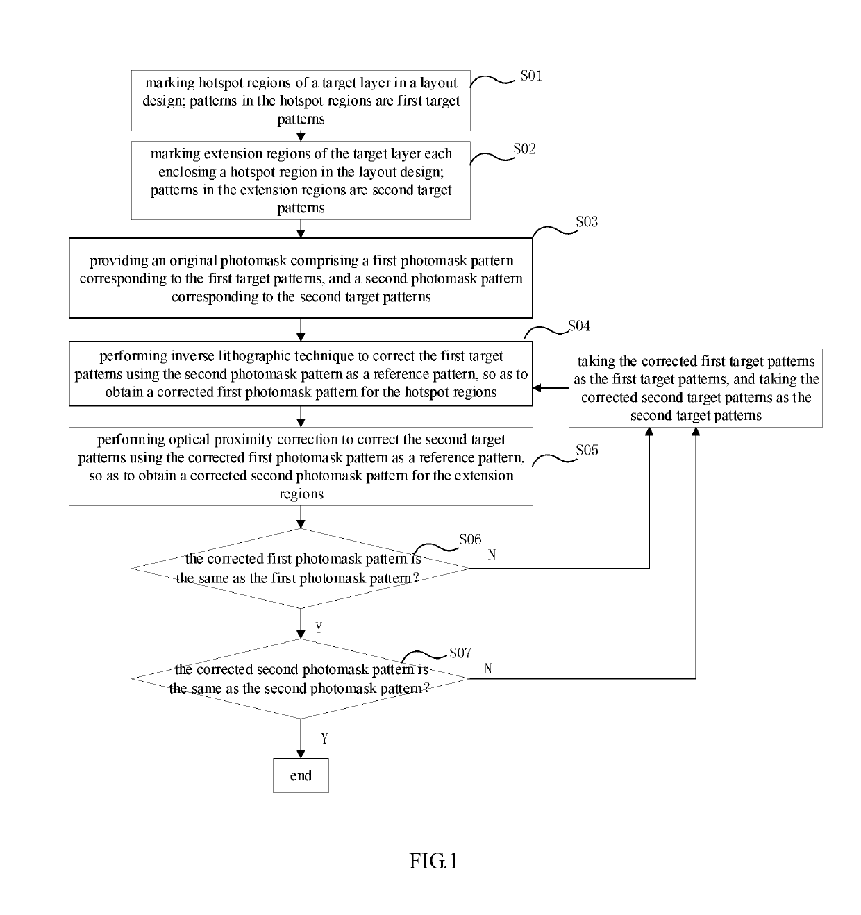
[0034]Referring to FIG. 1, the hotspot correction method comprises the following steps:

[0035]S01: marking hotspot regions of a target layer in a layout design.

[0036]Here, the target layer indicates a layer selected as being a target for correction to be formed on a wafer, such as a wiring layer. As mentioned above, layout patterns which conform the design rules and designed to be safe may be transferred into hotspots with insufficient process window during the actual manufacturing process. Accordingly, in this step, the locations of hotspots of the target layer with insufficient process window are defined in the layout design. The number of the hotspot can be one, or more. When more than one hotspot is defined, the hotspot regions and their extension regions will be corrected at the same time in the following steps.

[0037]After defining ...


PUM

PropertyMeasurementUnit
lengthaaaaaaaaaa
lengthaaaaaaaaaa
inner side lengthaaaaaaaaaa

Abstract

A hotspot correction method is provided. The layout patterns in the hotspot regions are accurately corrected by using an ILT method. Then the layout patterns in the extension regions are corrected by using an OPC method. As a result, the layout patterns in the hotspot regions can be accurately corrected while pattern distortion of the extension regions generated due to the regional ILT correction can be prevented. Moreover, high demanding of calculation capability and long calculation time of global ILT correction can be avoided.

Description

CROSS-REFERENCE TO RELAYED APPLICATION[0001]This application claims the priority benefit of China application serial no. 201710924604.9, filed Sep. 30, 2017. All disclosure of the China application is incorporated herein by reference.FIELD OF THE INVENTION[0002]The present invention relates to the field of semiconductor manufacturing, and more particularly to a lithographic hotspot correction method.BACKGROUND OF THE INVENTION[0003]With the continuing decrease of technology node, demands for pattern size precision and overlay accuracy are increasing. However, during the lithographic process, due to the resolution limitation of optical imaging, the right-angled pattern corner in the photomask layout will be inevitably subjected to rounding distortion when exposed and imagined on a silicon wafer. If not being corrected properly, such corner distortion will cause various problems like size reduction of the pattern corner, which will bring adverse effects on the overlay accuracy and the...

Claims


Application Information

Patent Timeline
Patent Type & Authority Applications(United States)
IPC IPC(8): G06F17/50G03F1/36
CPCG06F17/5081G03F1/36G03F7/70441G06F30/398
Inventor TAN, YIQUNYU, SHIRUIZHAO, XUAN
Owner SHANGHAI HUALI MICROELECTRONICS CORP
Why Eureka
Try Eureka