Laminated Moulded Parts and Manufacture Thereof

a technology of laminated moulded parts and manufacturing methods, applied in the direction of layered products, etc., can solve the problems of poor finish in the final painted components, difficult control of the moulding process, and difficulty in producing press-moulded net shape moulded parts from composite materials, etc., to achieve fast cure, high quality, and high quality a-surface

Inactive Publication Date: 2019-05-16
GURIT (UK) LTD
View PDF5 Cites 1 Cited by
  • Summary
  • Abstract
  • Description
  • Claims
  • Application Information

AI Technical Summary

Benefits of technology

[0019]The preferred embodiments of the present invention can provide the assembly of a net shaped preform in a mould, and then the preform is transferred to a press mould for press moulding. The use of press moulding allows a faster cure for the thermosetting resin than conventional autoclave processing which is used for the manufacture of composite material parts having a high quality surface finish as the press can be kept hot at the required cure temperature whereas in autoclave processing the tool is cycled between a relatively cool lay-up and a relatively hot cure temperature.
[0020]The preferred embodiments of the present invention can provide a net shaped preform which, after press moulding, exhibits in the final moulded part a high quality A-surface, and also a high quality B-surface. The moulded part has a smoothly rounded, beaded edge that just needs de-flashing (rather than machining) before coating with a clear lacquer finish coat.
[0021]The preferred embodiments of the present invention can enable the use of simple press mould tooling with a bulb feature to give a beaded edge feature without the need to have sliding tool parts to de-mould the component. This gives the advantage of a sealed and cosmetic pleasing edge w...

Problems solved by technology

A particular problem encountered with press moulding of an initial charge, or preform, of moulding material which at least partially comprises prepreg and/or SMC components, is that due to manufacturing tolerances in the initial charge the volume of the mould cavity is not always equal to the volume of the initial charge.
Consequently, it is difficult to control the moulding process, especially to produce a composite material part having a moulded shape and dimensions which, on exit from the mould, have very close tolerance to the desired final shape and dimensions of the ultimately manufactured part, i.e. a “net shape moulded part”.
This problem is particularly acute when the moulded part has fine edge details, not only because fine shape and dimensions need to be accurately moulded but also because exposed edges of the composite material must be sealed with resin, so that the fibres are no...

Method used


Image

  • Laminated Moulded Parts and Manufacture Thereof
  • Laminated Moulded Parts and Manufacture Thereof
  • Laminated Moulded Parts and Manufacture Thereof

Examples


example 1

[0089]A cosmetic carbon fibre component having a stack as described below in Table 1 was provided to form a central layer portion of a moulding material.

TABLE 1PlyProduct Description1SF-160 300 gsm300 gsm surfacing epoxy resin (160° C. Tg)2 + 3ST160 / NMAT / HSC / 100 / 60%100 gsm non-woven needled carbon fibre madefrom recovered carbon fibre consisting of amixture of fibres between 10 and 150 mm inlength with 60 wt % epoxy resin (160° C. Tg)content as a single-sided non-impregnatedprepreg4ST160 / XC300C / 51%300 gsm non crimp stitched biaxial carbon fibrefabric with 51 wt % epoxy resin (160° C. Tg)content as a single-sided non-impregnatedprepreg5 + 6ST160 / NMAT / HSC / 100 / 60%100 gsm non-woven needled carbon fibre madefrom recovered carbon fibre consisting of amixture of fibres between 10 and 150 mm inlength with 60 wt % epoxy resin (160° C. Tg)content as a single-sided non-impregnatedprepreg7SF-160 300 gsm300 gsm surfacing epoxy resin (160° C. Tg)

[0090]An edge filler resin paste was prepared by di...

example 2

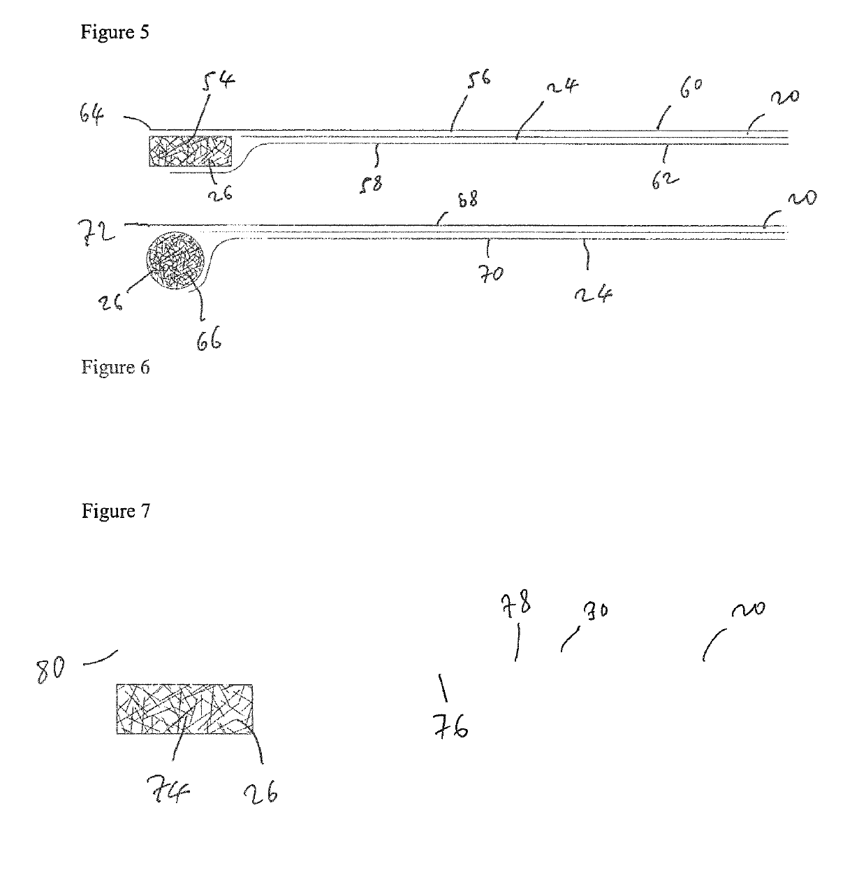
[0103]A test preform edge mould, and the cure process as in Example 1, were used but in combination with a modified moulding material having the structure and composition as shown in FIG. 6. Glass fibre fabric was employed rather than carbon fibre fabric. In this Example, a flat panel 240 was moulded and the central layer portion of the moulding material had substantially the same laminated construction as used for Example 1. The uppermost and lowermost fabric plies partially wrapped around the peripheral edge portion which comprised a rod of the edging paste comprising the short carbon fibres. The central ply was cut 2 mm shorter to accommodate the edging paste. The peripheral edge portion comprised the same edging paste, comprising epoxy resin, short carbon fibres, filler and pigment, as in Example 1.

[0104]FIG. 15 shows a micrograph, in both annotated and unannotated form, showing different regions in a cross section through the edge of a press moulded part 240 produced in accorda...


PUM

PropertyMeasurementUnit
Temperatureaaaaaaaaaa
Lengthaaaaaaaaaa
Lengthaaaaaaaaaa

Abstract

A method of moulding a moulding material to form a laminated moulded part of fibre-reinforced resin matrix composite material, the method comprising the steps of:
  • i. providing in a mould tool a preform comprising a central layer portion and a peripheral edge portion around at least a part of a periphery of the central layer portion, the central layer portion including at least one fibrous layer and a first resin, and the edge portion comprising a second resin including a plurality of individual fibres dispersed therein;
  • ii. closing the mould tool to define a closed mould cavity containing the moulding material; and
  • iii. applying heat and pressure to the mould cavity to cause the first and second resins to flow and to configure the moulding material in a fully moulded shape to form a laminated moulded part from the moulding material, wherein at least the first resin impregnates the at least one fibrous layer to form a central laminated portion of the laminated moulded part and wherein the second resin and the plurality of individual fibres dispersed therein flow to form a moulded edge of the laminated moulded part.

Description

FIELD OF THE INVENTION[0001]The present invention relates to a method of moulding a moulding material to form a laminated moulded part of fibre-reinforced resin matrix composite material, and to a laminated moulded part of fibre-reinforced resin matrix composite material. In particular, the present invention relates to such a method which is for manufacturing moulded parts composed of fibre reinforced resin matrix composite materials, such as, for example, panels, more particularly automotive body panels, having a high quality surface finish.BACKGROUND[0002]It is known to produce moulded parts for various applications, and having various shapes and configurations, by moulding materials including polymer resins, in particular for the manufacture of moulded parts composed of fibre reinforced resin matrix composite materials. Such composite materials are typically manufactured from moulding materials which may typically comprise, for example, (a) the combination of dry fibres and liqui...

Claims


Application Information

Patent Timeline
IPC IPC(8): B29C70/08B29C70/34
CPCB29C70/081B29C70/345B29C70/302B29B11/16B29C70/46B32B5/142
Inventor JONES, DANIEL THOMAS
Owner GURIT (UK) LTD
Why Eureka
Try Eureka