Detector for optically detecting at least one object

a detector and optical detection technology, applied in the direction of instruments, sustainable manufacturing/processing, radio frequency controlled devices, etc., can solve the problems of insufficient use of large area sensors in the use of fip measurement principle, insufficient beam splitter, and inability to achieve the effect of low requirements and low technical effor

Inactive Publication Date: 2019-05-23
TRINAMIX GMBH
View PDF0 Cites 24 Cited by
  • Summary
  • Abstract
  • Description
  • Claims
  • Application Information

AI Technical Summary

Benefits of technology

[0026]It is therefore an object of the present invention to provide devices and methods facing the above-mentioned technical challenges of known devices and methods. Specifically, it is an object of the pres...

Problems solved by technology

Despite the advantages implied by the above-mentioned devices and detectors, several technical challenges remain.
Still, large area sensors in many cases are inherently limited in the use of the FiP measurement principle, specifically in case more than one light spot is to be investigated simultaneously.
Thus, an expensive beam splitter is necessary.
Semitransparency, however, restricts the options of choice for both FiP-detectors and PSD materials.
Thus, transparency of FiP and/or PSD detectors remains a technical challenge.
However, in such an arrangement of FiP sensor deviations from a common optical axis of the stack may occur, such as angu...

Method used


Image

  • Detector for optically detecting at least one object
  • Detector for optically detecting at least one object
  • Detector for optically detecting at least one object

Examples


Embodiment Construction

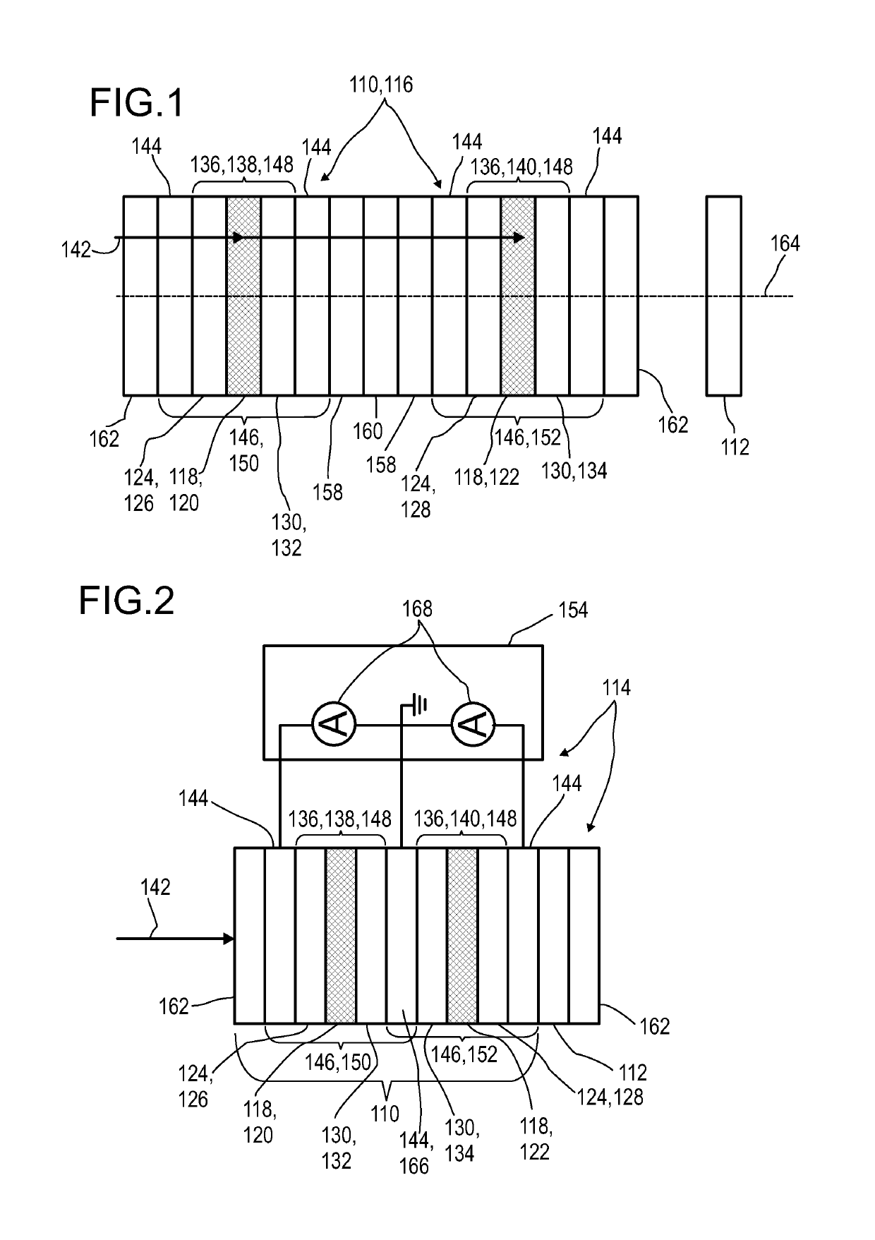
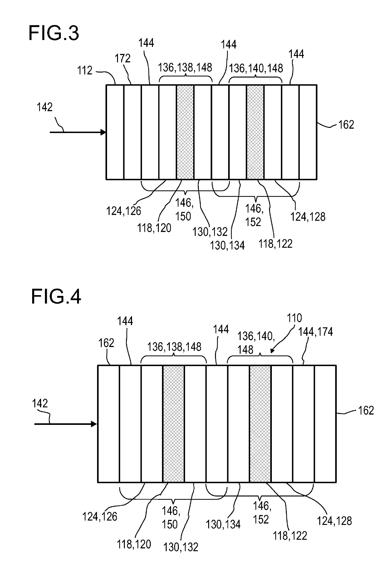
[0313]FIG. 1 shows, in a highly schematic illustration, an exemplary embodiment of a longitudinal optical sensor 110 and a transversal optical sensor 112 of a detector 114 according to the present invention. The longitudinal optical sensor 110 has a layer setup. The longitudinal optical sensor 110 may comprise at least two intrinsic semiconductor layers 118, for example a first intrinsic semiconductor layer 120 and a second intrinsic semiconductor layer 122. The longitudinal optical sensor 110 comprises at least two p-type semiconductor layers 124, for example, a first p-type semiconductor layer 126 and a second p-type semiconductor layer 128. The longitudinal optical sensor 110 comprises at least two n-type semiconductor layers 130, for example, a first n-type semiconductor layer 132 and a second n-type semiconductor layer 134. Each of the intrinsic semiconductor layers 118 may be located between one of the p-type semiconductor layers 124 and one of the n-type semiconductor layers ...


PUM


Abstract

A detector for determining a position of at least one object, in particular for 3D-sensing concepts, is disclosed. The detector comprises a longitudinal optical sensor (110) for determining a longitudinal position of an object by a light beam traveling from the object to the detector and a transversal optical detector (112) which may be designed as an imaging device or a position sensitive detector. The longitudinal sensor (110) has at least two PN structures or PIN structures (138, 140). Each of the PN structures or PIN structures is located between two electrode layers (144), thereby forming photodiodes (146) having a longitudinal sensor region (148) each. Longitudinal sensor signals from the photodiodes (146) are, given the same total power of illumination, are dependent on a beam cross-section of the light beam in the longitudinal sensor regions (148). As an alternative, instead of the transversal optical detector (112) the photodiodes (146) of the longitudinal optical sensor (110) may be adapted to operate as one-dimensional position sensitive detectors each, for determining a transversal x-coordinate and a transversal y-coordinate, respectively.

Description

FIELD OF THE INVENTION[0001]The invention relates to a detector, a detector system and a method for determining a position of at least one object. The invention further relates to a human-machine interface for exchanging at least one item of information between a user and a machine, an entertainment device, a tracking system, a camera, a scanning system, a method and various uses of the detector device. The devices, systems and uses according to the present invention specifically may be employed for example in various areas of daily life, gaming, traffic technology, production technology, security technology, photography such as digital photography or video photography for arts, documentation or technical purposes, medical technology or in the sciences. However, other applications are also possible.PRIOR ART[0002]A large number of optical sensors and photovoltaic devices are known from the prior art. While photovoltaic devices are generally used to convert electromagnetic radiation,...

Claims


Application Information

Patent Timeline
IPC IPC(8): H01L31/02G01S17/46G01S7/481H01L31/101H01L31/105H01L27/146
CPCH01L31/02024G01S17/46G01S7/4814G01S7/4816H01L31/1016H01L31/1055H01L27/14665H01L31/101Y02E10/541Y02P70/50H01L31/022475H01L31/022483H01L31/03046H01L31/0322H01L31/0326H01L31/0376
Inventor SEND, ROBERTBRUDER, INGMARLUNGENSCHMIED, CHRISTOPHHERMES, WILFRIEDVALOUCH, SEBASTIAN
Owner TRINAMIX GMBH
Why Eureka
Try Eureka