Systems for water extraction

a water extraction system and water technology, applied in membrane technology, reverse osmosis, membranes, etc., can solve the problems of low boron filtration efficiency, insufficient selectiveness insufficient energy consumption of water extraction techniques, so as to achieve high salt rejection, low energy consumption, and high water flux

Active Publication Date: 2019-06-20
AQUAPORIN AS
View PDF13 Cites 7 Cited by
  • Summary
  • Abstract
  • Description
  • Claims
  • Application Information

AI Technical Summary

Benefits of technology

[0005]It is an object of the present invention to provide a water extraction system utilizing aquaporin water channels immobilized in or on a supported filter membrane, such as in the form of a supported or immobilized liquid membrane formulation. With reference to FIG. 1 said system comprises a flow cell (1) comprising a membrane (2) where said membrane comprises an active layer (3) comprising aquaporin water channels and a porous support layer (4), and said membrane having a feed side (5) and a non-feed side (6); and said system further comprising an aqueous source solution (7) in fluid communication with said feed side. The present invention provides a novel system for selective water extraction, wherein a filter membrane incorporating aquaporin water channels, such as the aquaporin Z water channels, provide to the system the unique and selective water transporting properties of said channels, i.e. highly efficient water flux, high salt rejection, low energy consumption in forward osmosis operation mode, high rejection of small organic and inorganic solutes, intrinsic low fouling propensity, and robust operation conditions, especially of the membranes used in the system.

Problems solved by technology

However, with the growing scarcity of clean water, more and more interest is being paid to extraction of clean water from seawater and industrial water and to treatment of industrial process water and difficult wastewater streams.
However, these water extraction techniques are still energy-intensive and not always sufficiently selective.
Examples are contaminants, such as dissolved boron compounds naturally present in seawater and in contaminated groundwater, and which can pose a problem in desalinated water for irrigation and drinking water, and arsenic compounds that are frequently present in natural surface and ground water sources, e.g. in alluvial plains and moraine deposits.
However, this low boron filtration efficiency may necessitate several filtration cycles in order to obtain a desired low boron content in the resulting filtrate.

Method used


Image

  • Systems for water extraction
  • Systems for water extraction
  • Systems for water extraction

Examples


example 1

r Removal of Boron Contamination in a Freshwater Source Using FO and RO

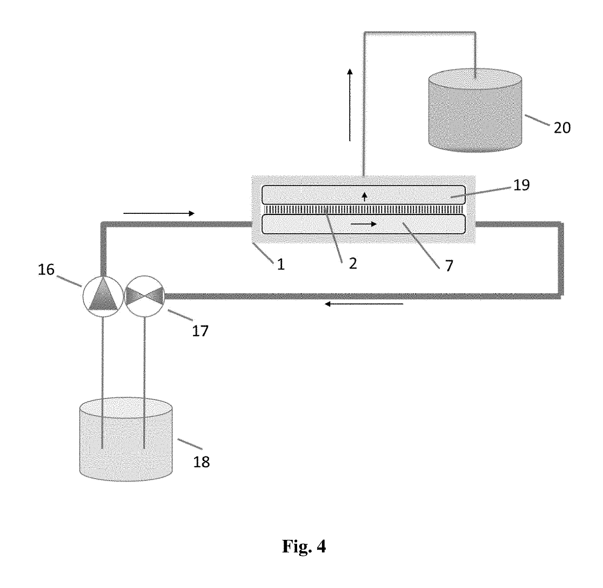
[0112]FIG. 4 shows a system for water extraction with boron removal using a Washguard SST pump (16) and an osmotic cell (Sterlitech CF042) for RO filtration, where said cell holds a 5.7 cm×11.3 cm TFC-AqpZ membrane prepared as described herein, and wherein a boron contaminated fresh water feed source created by dissolving boric acid to about 5 mg / L B in tap water having a mean content of 187 μg / L B, 0.20 μg / L As, 113 mg / L Ca, pH=7.5 (source: HOFOR, Copenhagen 2011) is filtered through said membrane during RO operation mode at a pressure of 125 psi. The resulting permeate can be sampled for ICP-MS boron elemental analysis, e.g. according to Nagaishi & Ishikawa (2009), giving a calculated rejection range based on the obtained analytical data of from about 45% to about 55% rejection comparable to the results obtained by Kim et al. 2012.

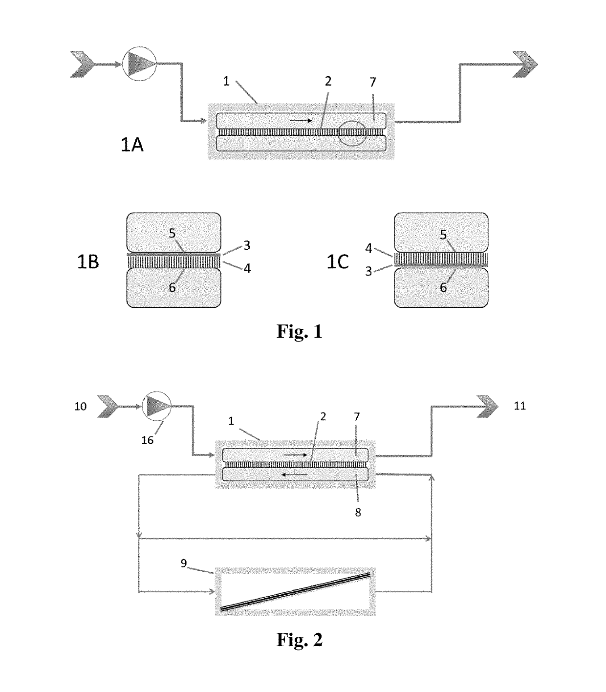
[0113]FIG. 2 shows a system for water extraction with boron removal using the sam...

example 2

r Removal of Arsenic Contamination in a Freshwater Source Using FO and RO

[0119]The same RO system as described in Example 1 was used except that an artificially created feed solution of 5 mg / L As (arsenic acid dissolved in MilliQ water and adjusted to pH 9.5 using 1N NaOH) is filtered through said membrane during RO operation mode at a pressure of 125 psi. The resulting permeate can be sampled for ICP-MS arsenic elemental analysis, e.g. as described by Grosser (2010), giving a calculated rejection range based on the obtained analytical data of about 100% rejection.

[0120]The same FO system as described in Example 1 was used except that a feed solution of 5 mg / L As in MilliQ water, pH 9.5, and a draw solution of 2M NaCl in MilliQ water was used. After 1300 min operation samples for arsenic elemental analysis were taken from the draw solutions for ICP-MS analysis. The results show that a calculated arsenic rejection based on the obtained analytical data of about 100% can be obtained us...

example 3

mprising an FO Concentrator Module, e.g. for Peptides

[0125]Method:

[0126]FO module is prepared by the following steps:[0127]1. water tight fastening, such as gluing with silicone glue or otherwise clamped tight, of a plastic measuring cylinder (such as having a diameter of 1 cm and the like depending on volume to be up-concentrated) to a Plexiglas surface with a corresponding hole of area 0.5 cm2 or 3.14 cm2, where the feed solution will be exposed to the membrane.[0128]2. A mesh support is glued immediately underneath.[0129]3. A TFC-AqpZ membrane, such as prepared using 1FPH support membrane and P8061 amphiphilic copolymer for the polymersomes, was prepared as described above, where active side on top is glued under the support or, alternatively, water tight fastened with O-ring.[0130]4. Optionally, a rubber gasket may be glued after the membrane.[0131]5. An additional rubber gasket can be added as a cushion when the top part is assembled with the bottom part where the tubing is pla...


PUM

PropertyMeasurementUnit
pressureaaaaaaaaaa
pressureaaaaaaaaaa
freezing pointaaaaaaaaaa

Abstract

The present invention relates to a water extraction system comprising a flow cell comprising a membrane; said membrane comprising an active layer comprising immobilized aquaporin water channels and a support layer, and said membrane having a feed side and a non-feed side; and an aqueous source solution in fluid communication with the feed side of the membrane.

Description

FIELD OF THE INVENTION[0001]The present invention relates to a system for water extraction said system comprising a flow cell housing a filter membrane, where said membrane has an active layer comprising immobilized aquaporin water channels, and a porous support layer, and where an aqueous source solution is in fluid communication with said membrane. In addition, the invention relates to systems for removal of contaminants from water sources, systems for generation of diluted nutrient solutions for irrigation purposes using fertilizer drawn forward osmosis, systems for concentrating organic and / or inorganic solutes in aqueous solutions, water extraction systems using forward osmosis and / or reverse osmosis in general, such as low pressure reverse osmosis, systems for pressure retarded osmosis, waste water or process water treatment including extraction of water from used dialysate solutions, and combined systems for desalination and / or energy generation having low or zero carbon emis...

Claims


Application Information

Patent Timeline
Patent Type & Authority Applications(United States)
IPC IPC(8): B01D71/74A61M1/16B01D71/56A01C23/04B01D61/00B01D61/02B01D61/08B01D65/02B01D67/00B01D69/10B01D69/12C02F1/44B01D69/14
CPCB01D71/74A61M1/1623B01D71/56A01C23/042B01D61/002B01D61/025B01D61/08B01D65/02B01D67/0093B01D69/10B01D69/125C02F1/445C02F1/441B01D69/144B01D2323/30B01D2321/162B01D2321/168C02F2101/108C02F2101/16C02F2103/08Y02W10/37Y02P60/214Y02P60/21
Inventor MENTZEL, SORENPERRY, MARK EDWARDVOGEL, JORGBRAEKEVELT, SYLVIEGESCHKE, OLIVERLARSEN, MARIANNE ELEONORA SPANGET
Owner AQUAPORIN AS
Why Eureka
Try Eureka