Contactless power receiving device, contactless power transfer device, and contactless power transfer and receiving device

a technology of contactless power and receiving device, which is applied in the direction of dc-ac conversion without reversal, charging station, transportation and packaging, etc., can solve the problems of poor transmission efficiency of wireless power transfer technology using a microwave, troublesome connection of a charging connector at the time of charging of a built-in battery, and hardly put into practical use. , to achieve the effect of low conversion efficiency, high conversion efficiency and low conversion efficiency

Active Publication Date: 2019-06-20
MAXELL HLDG LTD
View PDF0 Cites 13 Cited by
  • Summary
  • Abstract
  • Description
  • Claims
  • Application Information

AI Technical Summary

Benefits of technology

[0016]Further, among the plurality of combinations, the input voltage sometimes converges to the input voltage value which causes the DC-DC converter to operate in a state of low conversion efficiency. For example, in a case of a step-down type DC-DC converter, the conversion efficiency is highest when the input voltage is slightly higher than the output voltage, and the conversion efficiency tends to be lower as the input voltage becomes higher. Therefore, it is desirable that the input voltage of the DC-DC converter converges to the value slightly higher than the output voltage from the viewpoint of efficiency. However, depending on the matching state between the DC-DC converter and the rectifier circuit and the matching state between the power transfer coil and the power receiving coil, the input voltage sometimes converges to the value higher than the output voltage. In this case, the DC-DC converter operates in the state of low conversion efficiency.
[0017]Further, depending on the matching state, the input voltage sometimes converges to the input voltage value that is lower than the output voltage of the DC-DC converter and is incapable of causing the DC-DC converter to operate among the plurality of combinations, so that the phenomenon in which the normal operation is impossible occurs. Namely, depending on the matching state, the DC-DC converter cannot operate stably and efficiently in some cases.

Problems solved by technology

When the reduction in size and thickness has advanced, the connection of a charging connector at the time of charging of a built-in battery becomes troublesome.
Also, in the case of the wired charging for a built-in battery of an electric vehicle, water may enter the charging connector at the time of rain and the contact point may be deteriorated, and thus the charging by the wireless power transfer technology has been desired.
However, the wireless power transfer technology using a microwave is poor in transmission efficiency, and is hardly put into practical use.

Method used


Image

  • Contactless power receiving device, contactless power transfer device, and contactless power transfer and receiving device
  • Contactless power receiving device, contactless power transfer device, and contactless power transfer and receiving device
  • Contactless power receiving device, contactless power transfer device, and contactless power transfer and receiving device

Examples


first embodiment

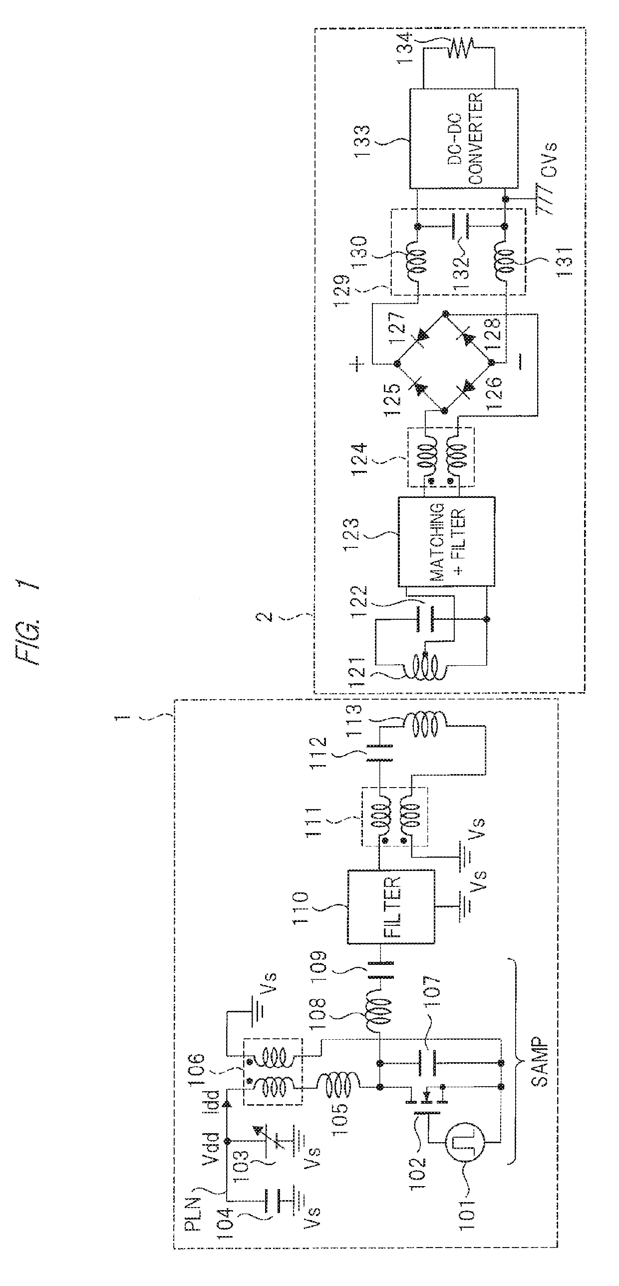
[0054]FIG. 1 is a circuit diagram showing a configuration of a contactless power transfer and receiving device according to a first embodiment. In FIG. 1, 1 denotes a contactless power transfer device and 2 denotes a contactless power receiving device. The contactless power transfer device 1 and the contactless power receiving device 2 are coupled by inductive coupling.

[0055]

[0056]First, a configuration of the contactless power transfer device 1 will be described. The contactless power transfer device 1 includes a drive power supply 101, a field effect transistor (hereinafter, referred to also as MOSFET) 102, a variable voltage power supply 103, a ground capacitance element 104, a choke coil 105, common mode filters 106 and 111, capacitance elements 107 and 109, an inductor 108, a filter 110, a resonant capacitance element 112, and a power transfer coil 113.

[0057]In the first embodiment, though not particularly limited, a power transfer amplifier SAMP is composed of the drive power ...

second embodiment

[0143]FIG. 14 is a circuit diagram showing a configuration of a contactless power transfer and receiving device according to a second embodiment. Since FIG. 14 is similar to FIG. 1, the difference therebetween will be mainly described. Since a configuration of a contactless power transfer device 1-1 is the same as that of the contactless power transfer device 1 shown in FIG. 1, the description thereof will be omitted.

[0144]In the contactless power receiving device 2 shown in FIG. 1, the rectifier circuit is composed of a bridge type full-wave rectifier including the rectifier diodes 125 to 128. Also, the smoothing circuit 129 is composed of the two inductors 130 and 131 and the smoothing capacitance element 132. Meanwhile, in a contactless power receiving device 2-1 shown in FIG. 14, the rectifier circuit is composed of a voltage doubler circuit including rectifier diodes 201 and 202. In addition, a smoothing circuit 203 is composed of an inductor 204 and a smoothing capacitance ele...

third embodiment

[0149]FIG. 15 is a circuit diagram showing a configuration of a contactless power transfer and receiving device according to a third embodiment. The contactless power transfer and receiving device according to the third embodiment includes a contactless power transfer device 1-2 and a contactless power receiving device 2-2. Since the contactless power transfer device 1-2 and the contactless power receiving device 2-2 are similar to the contactless power transfer device 1 and the contactless power receiving device 2 shown in FIG. 1, the difference therebetween will be mainly described.

[0150]First, the contactless power transfer device 1-2 will be described. As in the contactless power transfer device 1 shown in FIG. 1, the contactless power transfer device 1-2 includes the power transfer amplifier SAMP, the common mode filter 111, the resonant capacitance element 112, and the power transfer coil 113. Also, a modulation demodulation circuit (second modulation demodulation circuit) 311...


PUM


Abstract

A contactless power receiving device includes a power receiving coil receiving power from a contactless power transfer device, a rectifier circuit rectifying the power to form a rectified output on a high potential side and a rectified output on a low potential side, a smoothing circuit receiving the rectified output on the high potential side and the rectified output on the low potential side, and a switching power supply converting a DC voltage from the smoothing circuit to a first voltage. The smoothing circuit includes a first inductor transmitting the rectified output on the high potential side, a second inductor transmitting the rectified output on the low potential side, and a smoothing capacitance element to which the rectified output on the high potential side and the rectified output on the low potential side are supplied, and the rectified output on the low potential side is connected to a ground potential.

Description

TECHNICAL FIELD[0001]The present invention relates to a wireless power transfer technology and relates to, for example, a contactless power receiving device, a contactless power transfer device, and a contactless power transfer and receiving device relative to a contactless power transfer technology for contactlessly charging batteries of portable terminals such as mobile devices and electric vehicles.BACKGROUND ART[0002]In recent years, portable terminals such as mobile devices have been reduced in size and thickness. When the reduction in size and thickness has advanced, the connection of a charging connector at the time of charging of a built-in battery becomes troublesome. Therefore, the demand for charging by the wireless power transfer technology has been increasing. Also, in the case of the wired charging for a built-in battery of an electric vehicle, water may enter the charging connector at the time of rain and the contact point may be deteriorated, and thus the charging by...

Claims


Application Information

Patent Timeline
Patent Type & Authority Applications(United States)
IPC IPC(8): H02J50/12H02J7/02H02M7/46H02M7/06H01F38/14
CPCH02J50/12H02J7/025H02M7/46H02M7/06H01F38/14H02J50/80B60L53/12B60L2270/147H02M7/4815H02J50/10
Inventor KAWAMAE, OSAMUICHIKAWA, KATSUEI
Owner MAXELL HLDG LTD
Why Eureka
Try Eureka