Ice detection/protection and flow control system based on printing of dielectric barrier discharge sliding plasma actuators
Inactive Publication Date: 2019-06-27
UNIVE BEIRA INTERIOR
View PDF0 Cites 7 Cited by
- Summary
- Abstract
- Description
- Claims
- Application Information
AI Technical Summary
Benefits of technology
The invention is a new ice control system for aircraft that prevents ice formation and deices the surfaces of the aircraft. It uses a unique ice detection system and an anti-icing / deicing mechanism based on a three-electrode configuration. The system has low power consumption, increases performance, and requires little maintenance. It can be used as an actuator for flow control and surface heating. The system is efficient and can be used in large scale applications. It also integrates ice sensors to gather more information and improve system efficiency. Overall, the invention is a more effective and efficient solution for preventing ice accumulation on aircraft surfaces.
Problems solved by technology
Although this system uses DBD plasma actuators to perform deicing, it does not use the DBD plasma actuator as an ice detector sensor.
In addition, the area covered by the actuator is limited, and since it contains only one electrode exposed per actuator, it does not contain any type of mechanism to control the accumulation of ice in the area that is not effectively heated by the actuator.
Although DBD plasma actuators are used in the above system to perform deicing, this type of system does not include an ice detector sensor.
On the other hand, the area encompassed per actuator is limited and, since it only contains an electrode exposed per actuator, it does not contain any type of mechanism to control the accumulation of ice in the area that is not effectively heated by the actuator.
Although the above system makes use of DBD plasma actuators for performing deicing, this system does not include an ice detector sensor, the area covered per actuator is limited and, since it only has one exposed electrode per actuator, it does not contain any type of mechanism to control the accumulation of ice in the area that is not effectively heated by the actuator.
Although the above system makes use of DBD plasma actuators for performing deicing, this system does not include an ice detector sensor, the area covered per actuator is limited and, since it only has one exposed electrode per actuator, it does not contain any type of mechanism to control the accumulation of ice in the area that is not effectively heated by the actuator.
Although the above system makes use of DBD plasma actuators for performing deicing, also in this case, the system presented does not include an ice detector sensor, the area covered per actuator is limited and, since it only has one exposed electrode per actuator, it does not contain any type of mechanism to control the accumulation of ice in the area that is not effectively heated by the actuator.
Although the above system makes use of DBD plasma actuators for performing deicing, this system does not include an ice detector sensor, the area covered per actuator is limited and, since it only has one exposed electrode per actuator, it does not contain any type of mechanism to control the accumulation of ice in the area that is not effectively heated by the actuator.
Although the above system makes use of DBD plasma actuators for performing deicing, this system does not include an ice detector sensor, the area covered per actuator is limited and, since it only has one exposed electrode per actuator, it does not contain any type of mechanism to control the accumulation of ice in the area that is not effectively heated by the actuator.
The area of plasma extension is limited because it does not provide for the use of a sliding electrode that allows to increase the plasma extension and does not yet foresee the use of shock waves that prevent the aggregation of ice in areas that are not effectively heated by the operation of plasma actuators.
On the other hand, the presented system does not provide any functionality for detecting ice formation.
The system presented uses conventional plasma actuators, which does not provide for the use of a three-electrode plasma actuator, with a sliding electrode for increasing the plasma extension, and shock-wave generation functionality to expel the ice from the area that is not effectively heated by the actuator.
In addition, the system disclosed in said document does not also have an ice detection capacity.
These systems are limited only to detecting ice thickness.
Method used
View moreImage
Smart ImageViewing Examples
Examples
application examples
[0085]The present invention has various industrial applications such as deicing and flow control in aircraft components including fixed wings, stabilizers, jet engine inlet, engine inlet, helicopter rotor blades, rotary blades, air turbine blades.
[0086]It can also be applied as a deicing system in critical tubular systems.
Login to View More PUM
 Abstract
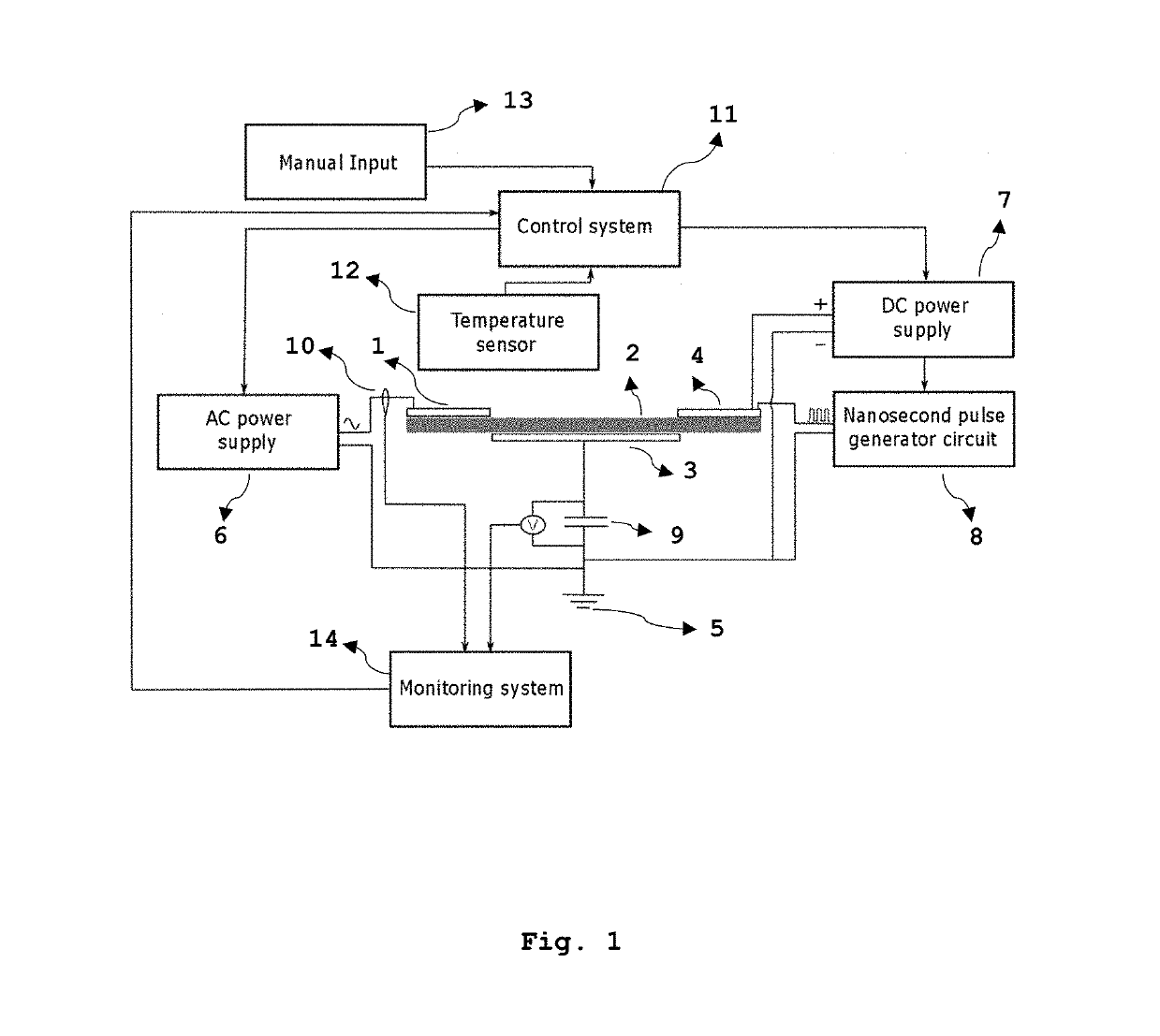
The present invention relates to an ice detection / protection and flow control system based on printing of dielectric barrier discharge sliding plasma actuators. This invention has advantages such as: reduced weight, low maintenance cost, no environmental impact, fully electric operation and combination of functionalities (ice detection, deicing, anti-icing and flow control).The system comprises the following components: exposed AC electrode (1), dielectric layer (2), embedded electrode (3), sliding / nanosecond electrode (4), ground plane (5), AC power supply (6), DC power supply (7), nanosecond range pulse generator (8), monitoring capacitor (9), high voltage probe (10), control module (11), temperature sensor (12), control signal input module (13) and monitoring system (14). The system senses ice formation and generates extensive surface heating to prevent ice accumulation.
Description
TECHNICAL DOMAIN[0001]The present invention relates to a smart ice detection, and protection and flow control system based on printing of dielectric barrier discharge sliding plasma actuators.SUMMARY[0002]The present invention discloses a system capable of controlling the flow and simultaneously performing ice detection, preventing ice formation and deicing on surfaces by making use of a dielectric barrier discharge sliding plasma actuator.[0003]Generally, most in-flight aircraft deicing and anti-icing methods only protect the surfaces and the most critical components of the aircraft. The present invention is useful for detecting and preventing the formation of ice on aircraft surfaces and has the following main advantages: reduced weight, low maintenance cost, no environmental impact, an electronic operation and the combination of a deicing and anti-icing system with a flow control system and ice detection sensors.[0004]The present invention can be applied to any type of surfaces w...
Claims
Login to View More Application Information
Patent Timeline
 IPC IPC(8): B64D15/22B64D15/12B64C23/04H05B1/02H05H1/24
CPCB64D15/22B64D15/12B64C23/04H05B1/0236H05H1/2406H05H2001/2412B64C2230/12B64C23/005B64D15/20H05B6/62H05B2214/02Y02T50/10H05H1/2439
Inventor ABDOLLAHZADEHSANGROUDI, MOHAMMADMAHDIPASCOA MARQUES, JOSE CARLOSFREIRE RODRIGUES, FREDERICO MIGUEL
Owner UNIVE BEIRA INTERIOR
Features
- R&D
- Intellectual Property
- Life Sciences
- Materials
- Tech Scout
- Unparalleled Data Quality
- Higher Quality Content
- 60% Fewer Hallucinations
Learn More Browse by: Latest US Patents, China's latest patents, Technical Efficacy Thesaurus, Application Domain, Technology Topic, Popular Technical Reports.
© 2025 PatSnap. All rights reserved.Legal|Privacy policy|Modern Slavery Act Transparency Statement|Sitemap|About US| Contact US: help@patsnap.com


