Thermally conductive member

a technology of thermally conductive parts and sponges, applied in the direction of electrical apparatus construction details, light and heating apparatus, printed circuit aspects, etc., can solve the problems of increasing the processing speed of a microprocessor, reducing the efficiency and limiting the elasticity of elastic bodies or sponges to not adequately use elasticity, etc., to achieve efficient and reliable performance of thermally conductive functions and simple structure

Inactive Publication Date: 2019-06-27
JOINSET
View PDF0 Cites 3 Cited by
  • Summary
  • Abstract
  • Description
  • Claims
  • Application Information

AI Technical Summary

Benefits of technology

[0019]The present invention is directed to providing a thermally conductive member capable of

Problems solved by technology

As electronic communication devices including cellular phones have been advanced and highly functional, a processing speed of a microprocessor increases such that electromagnetic waves and heating rear up as big problems.
According to the patents, since the polymer film or the base films surround the thermally conductive elastic body or the sponge, respectively, elasticity of the elastic body or the sponge is limited not to adequately use elasticity and the elastic body or the sponge may not be adequately surrounded or much time and cost are necessary to surround them when the elastic body or the sponge is manufactured while having a variety of shapes.
Also, since the metal layer or the graphite layer is formed the polymer film or the base film above the elastic body or the sponge, when being repeatedly pressed by a force applied in a vertical direction and being much pressed, a side surface of the metal layer or the graphite layer without elasticity is distorted or broken.
Also, being applied to an earphone including a voice coil oscillating due to an electrical signal, when the polymer film or the base film having a smooth surface and high mechanical strength comes into direct contact with a heating source or an obj

Method used


Image

  • Thermally conductive member
  • Thermally conductive member
  • Thermally conductive member

Examples


Embodiment Construction

[0040]Hereinafter, the present invention will be described in detail with reference to the attached drawings.

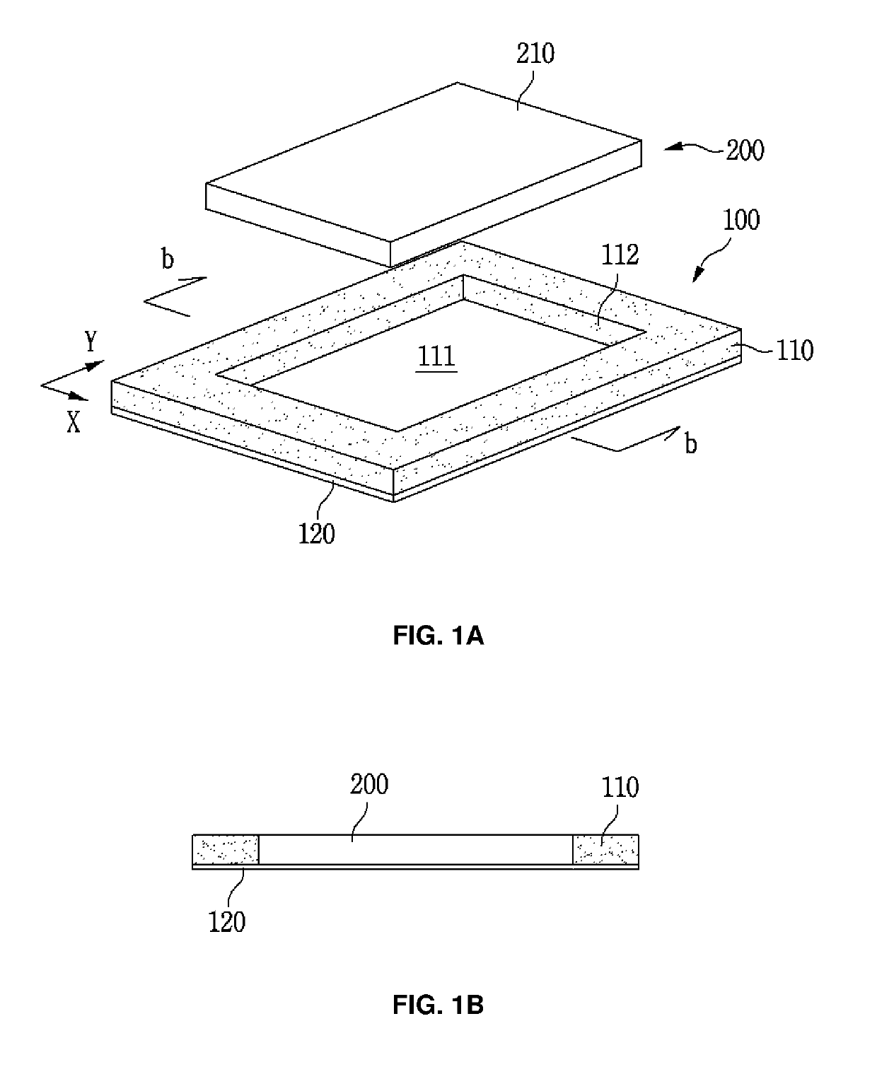
[0041]FIG. 1A illustrates a thermally conductive member according to one embodiment of the present invention, and FIG. 1B is a cross-sectional view taken along a line b-b.

[0042]The thermally conductive member includes a body 110 with a through hole 112, a thermally conductive support 120 bonded to a bottom surface of the body 110, a thermally conductive element 200 inserted into and combined with the through hole 112.

[0043]The body 110 forms a container 100 with the support 120, which adheres to the bottom surface thereof, and accommodates the thermally conductive element 200 in an accommodation space 111 in the container 100.

[0044]Hereinafter, a structure and a function of each of components will be described.

[0045]1. Body 110

[0046]The body 110 is a foaming body which has pores to have high elasticity and restoring force and a great elastically-operational distance and to be...


PUM

PropertyMeasurementUnit
Thicknessaaaaaaaaaa
Viscosityaaaaaaaaaa
Adhesion strengthaaaaaaaaaa

Abstract

Disclosed is a thermally conductive member capable of reliably performing a thermally conductive function with a simple structure. The thermally conductive member includes a container including an elastic body with a through hole passing through a top surface and a bottom surface thereof in a thickness direction and a thermally conductive support adhering to the bottom surface of the body and a thermally conductive element inserted or filled in an accommodation space formed by the through hole and the support and having self adhesion.

Description

REFERENCE TO RELATED APPLICATIONS[0001]This application claims priority to and the benefit of Korean Patent Application No. 2017-0179617, filed on Dec. 26, 2017 and 2018-0058656, filed on May 23, 2018, the disclosure of which are incorporated herein by reference in its entirety.FIELD OF THE INVENTION[0002]The present invention relates to a thermally conductive member.BACKGROUND OF THE INVENTION[0003]As electronic communication devices including cellular phones have been advanced and highly functional, a processing speed of a microprocessor increases such that electromagnetic waves and heating rear up as big problems.[0004]To solve the problems, for example, a cooling unit is generally used for discharging heat generated by a microprocessor to the outside.[0005]A heat dissipation unit is used while being interposed between, for example, a case for cooling and an electronic component mounted on a circuit board. For example, one surface of a thermal interface materials (TIM) having fle...

Claims


Application Information

Patent Timeline
IPC IPC(8): F28F21/02H05K7/20H05K9/00H05K1/02F28F21/06F28F21/08
CPCF28F21/02H05K7/20436H05K9/0083H05K9/0024H05K1/0203F28F21/065F28F21/067F28F21/089H05K2201/066H05K2201/10371H01L23/367H01L23/40H01L23/3735H01L2023/4075H01L23/42H05K7/20454H05K9/0029
Inventor KIM, SUN-KIKIM, SUNG-HOONLEE, HYUN-ILLLEE, SEONG-JINKIM, JIN-SAN
Owner JOINSET
Why Eureka
Try Eureka