Method for producing hollow structure, plated composite and hollow structure

a technology of composite and hollow structure, which is applied in the direction of manufacturing rigid-tube cables, semiconductor/solid-state device details, liquid/solution decomposition chemical coating, etc. it can solve the problems of limited type or number of mounted devices, increase the space occupied by the whole cooling fan or heat sink in the apparatus, etc., and achieve the effect of reducing the diameter, adjusting the strength, heat capacity and weight of the formed skeletal parts

Active Publication Date: 2019-07-18
ASAHI DENKA KENKYUSHO
View PDF4 Cites 4 Cited by
  • Summary
  • Abstract
  • Description
  • Claims
  • Application Information

AI Technical Summary

Benefits of technology

[0033]According to the present invention, it is possible to produce the hollow structure having the hollow part therein, without mechanically assembling heat-transfer thin sheets and so on. In this case, by appropriately setting the shape and thickness of the used core and the thickness of the plating layer covering the core, it is possible to produce a hollow structure having a complicated shape and a hollow structure which is downsized, thinned, and reduced in diameter as a whole. Further, by appropriately selecting the thickness of the core (“thickness” includes “diameter” in a case where the core is bar-shaped or cylindrical) and its shape, it is possible to arbitrarily set the size of the sectional area of the formed hollow part and the space volume of the whole hollow part. Further, by appropriately setting the thickness of the plating layer, it is possible to arbitrarily adjust the strength, heat capacity, and weight of the formed skeletal part. Further, if a method to melt and remove the core by heat is adopted, especially in a case of a structure having a narrow hollow part and a long depth, a solvent in which the core is molten is cooled to be solidified before being discharged out and thus cannot be smoothly discharged, and may remain in the space in a relatively large amount. On the other hand, in the present invention, since the core is dissolved by the solvent, the core is not solidified during a process of discharging it, and can be quickly discharged with almost no residue of the solvent of the core in the hollow part. This makes the present invention suitable for producing a thin hollow structure and a hollow structure having a complicated shape like those described above.
[0034]In particular, using the core having the through hole in the thickness direction is preferable because, in the formed skeletal part, the cylindrical plating layer is formed also on a wall surface of the through hole, and its upper and lower ends are coupled to and integrated with the plating layers respectively forming an upper surface portion and a lower surface portion of the skeletal part, so that, between the plating layers as the upper surface portion and the lower surface portion in the obtained hollow structure, this cylindrical plating layer also exhibits a reinforcing operation as a thickness-direction stay which prevents deflection.
[0035]Further, the hollow structure of the present invention achieves downsizing, a diameter reduction, thinning, and a weight reduction as a radiator such as a heat sink, a heat pipe, or a vapor chamber. Further, being capable of having an extremely thin or slender structure, it is suitable especially as a radiator loaded or built in various kinds of electronic apparatuses (electric control machines and apparatus, power distribution or control machines and apparatus, telecommunication machines and apparatus, portable information terminals, smartphones, computers, power modules, other electronic appliances, and so on) which require downsizing. Further, in a case where the present invention is applied to a cable (in particular, a high-speed transmission cable) for transmitting power or information, permittivity is stable all over the length because the cable can be a thin hollow structure, which is suitable for high-speed transmission of a large volume of data.

Problems solved by technology

This results in an increased space occupied by the whole cooling fan or heat sink in the apparatus, which involves a problem that the kind or the number of mounted devices is limited.

Method used


Image

  • Method for producing hollow structure, plated composite and hollow structure
  • Method for producing hollow structure, plated composite and hollow structure
  • Method for producing hollow structure, plated composite and hollow structure

Examples


Embodiment Construction

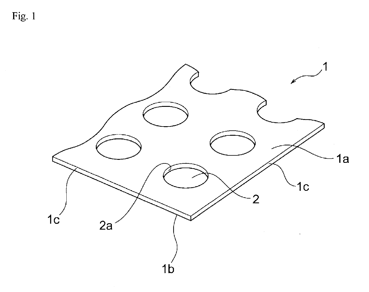
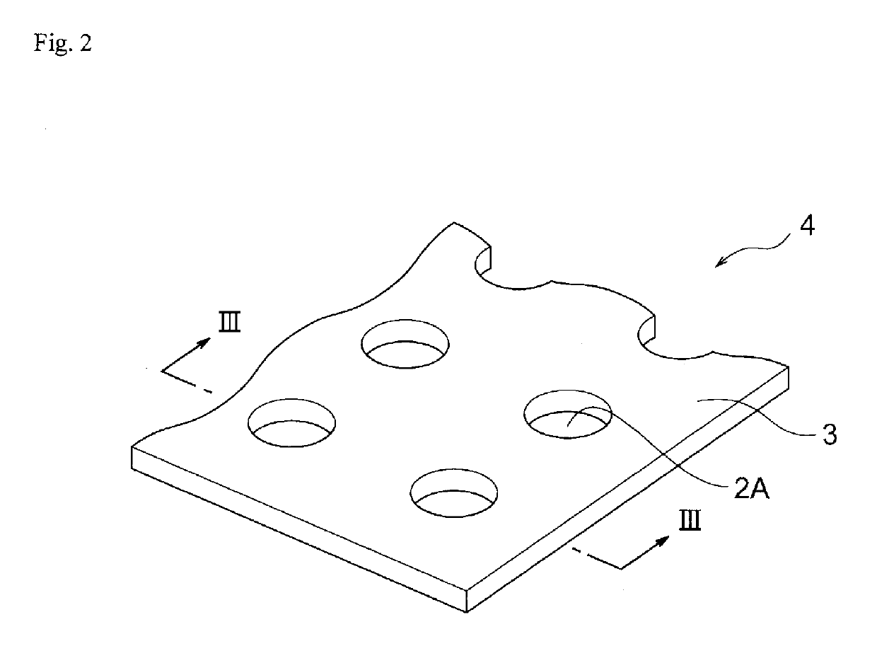
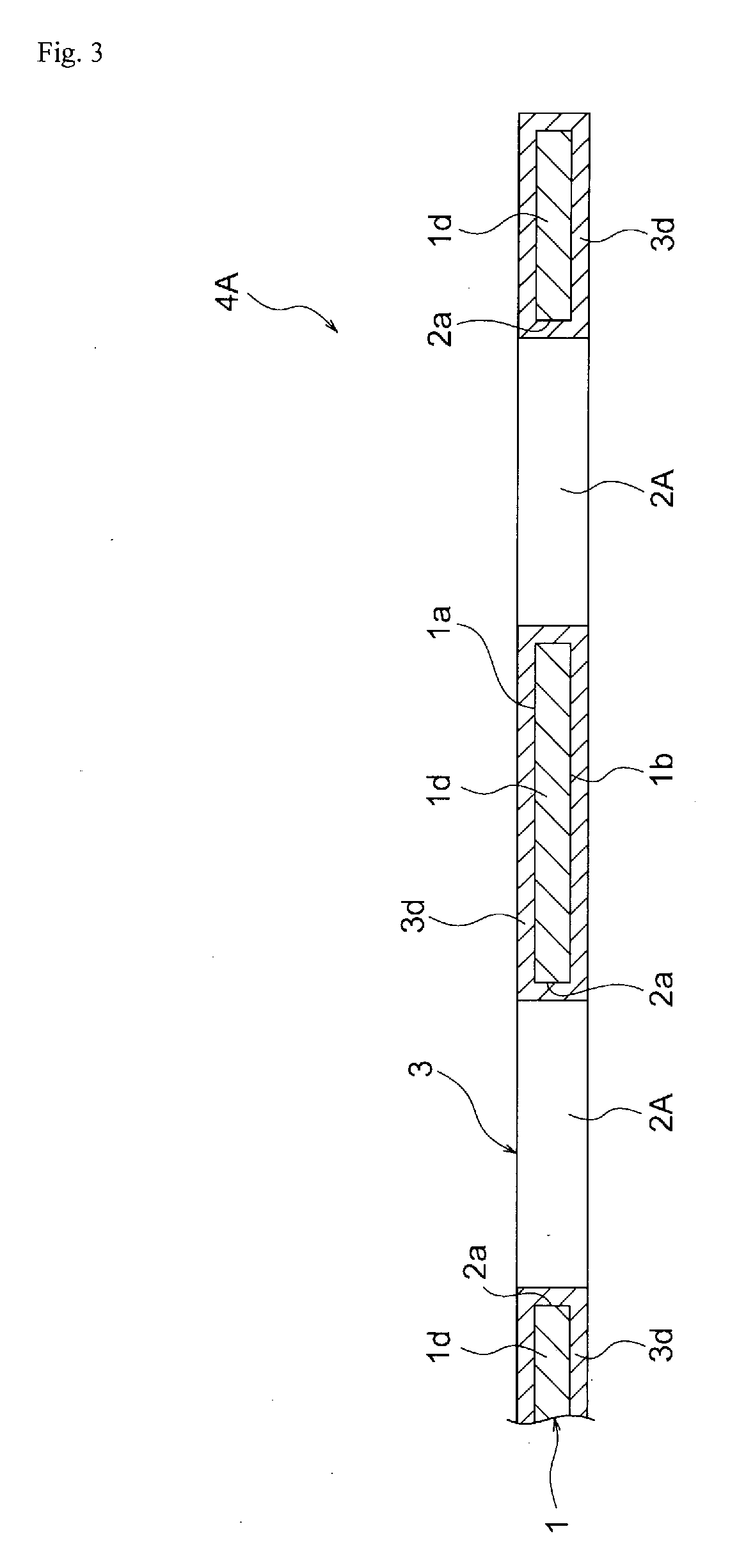
[0044]To produce a hollow structure, a later-described core is first prepared. In this embodiment, a plating layer covering the whole surface of the core is formed, and the plating layer is partly cut off, whereby a plated composite in which a cut surface of the core is exposed is produced.

[0045]Next, the plated composite whose core is partly exposed is immersed in a later-described solvent, whereby only the core is selectively dissolved and removed. Due to this immersion process, in the finally obtained hollow structure, a part corresponding to the core of the plated composite is turned into a hollow part and the plating layer is left as it is, so that a skeletal part having an integrated structure composed of a plating layer as an upper surface portion, a plating layer as a lower surface portion, and a cylindrical plating layer (in a case where a through hole is formed in the core) coupling the both plating layers is formed.

[0046]What is important here is the selection of a materi...


PUM

PropertyMeasurementUnit
thicknessaaaaaaaaaa
timeaaaaaaaaaa
temperatureaaaaaaaaaa

Abstract

A method for producing a hollow structure useful as a base material for a heat sink or the like which increases a heat dissipation property of devices mounted in various kinds of electronic apparatuses, without sacrificing downsizing, thinning, weight reduction, and multifunctionality, and provides a hollow structure. The method including: producing a plated composite by coating a surface of a core made of aluminum to form a copper plating layer; cutting off part of the plated composite to expose cut surfaces of the core; and turning a part corresponding to the core into a hollow part by immersing the plated composite in a sodium solution which dissolves aluminum but does not dissolve copper and selectively dissolving and removing only the aluminum, thereby producing a hollow structure whose skeletal part is composed of all copper plating layers.

Description

TECHNICAL FIELD[0001]The present invention relates to a method for producing a hollow structure useful as a radiator (a heat sink, a heat pipe, a vapor chamber) or the like assembled in various small, thin, and multifunctional semiconductor devices and to a plated composite and a hollow structure. More particularly, it relates to a method for producing a hollow structure which is developed using metal as a temporary plating core, a joining method of plating this metal with another kind of metal, and a difference in solubility in a specific solvent between these metals, and to a plated composite, and a hollow structure.BACKGROUND ART[0002]As various kinds of portable information terminals and electronic apparatuses such as desktop personal computers, tablets, and smartphones are rapidly becoming smaller, thinner, more multifunctional, and lighter-weighted, their information processing volumes and information transmission volumes are increasing and their information processing speeds ...

Claims


Application Information

Patent Timeline
Patent Type & Authority Applications(United States)
IPC IPC(8): C23C18/16C23C18/38C23C18/18C25D5/44C25D3/38
CPCC23C18/1657C23C18/1637C23C18/1641C23C18/1646C23C18/38C23C18/1834C25D5/44C25D3/38C23C18/1689C23C18/54C23F1/04C23F1/36C23F1/44C25D1/02C25D1/08H01L21/4871H01L23/367H01L23/3736H01L23/427H01B13/004C23F1/00C25D5/48
Inventor MIZOGUCHI, MASANORI
Owner ASAHI DENKA KENKYUSHO
Why Eureka
Try Eureka