
Methods of bandgap analysis and modeling for high k metal gate

a technology of high-k metal gates and band gaps, applied in individual semiconductor device testing, semiconductor/solid-state device testing/measurement, instruments, etc., can solve the problems of inherently slow throughput, limited penetration depth, and great challenge in linking physical thickness or composition

Inactive Publication Date: 2019-08-08
GLOBALFOUNDRIES US INC +1
View PDF0 Cites 2 Cited by
  • Summary
  • Abstract
  • Description
  • Claims
  • Application Information

AI Technical Summary

Benefits of technology

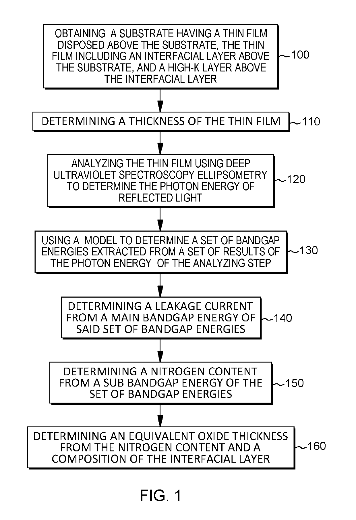
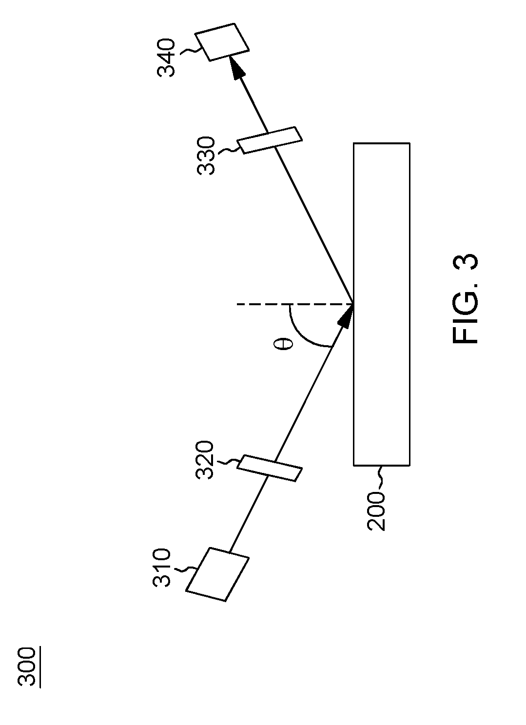
The patent text describes a method for analyzing a thin film on a substrate using deep ultraviolet spectroscopy ellipsometry to determine its thickness and determine the energy of reflected light. The method can also be used to determine the nitrogen content of the thin film and the composition of its interfacial layer. The technical effect of this method is to provide a reliable and accurate way to analyze thin films, which can be useful in various fields such as electronics, sensors, and optics.

Problems solved by technology

There is a great challenge in linking the physical thickness or the composition to the electrical properties using previous techniques due to the complexities.
For instance, inline X-ray photoelectron spectroscopy (XPS) has been used to determine the film composition, such as the nitrogen concentration, but the throughput is inherently slow and its penetration depth is limited, and no other film electrical properties can be provided.
Other compositional measurement techniques, such as offline secondary ion mass spectrometry (SIMS), can be destructive and extremely slow.
No electrical properties can be obtained either by SIMS, XPS, or other previous measurement techniques.
Additionally, studying the electrical parameters typically requires the full building of end transistor devices in order to measure and quantify results, which may take two to four months.

Method used


Image

  • Methods of bandgap analysis and modeling for high k metal gate
  • Methods of bandgap analysis and modeling for high k metal gate
  • Methods of bandgap analysis and modeling for high k metal gate

Examples


Embodiment Construction

[0017]Aspects of the present invention and certain features, advantages, and details thereof, are explained more fully below with reference to the non-limiting embodiments illustrated in the accompanying drawings. Descriptions of well-known materials, fabrication tools, processing techniques, etc., are omitted so as to not unnecessarily obscure the invention in detail. It should be understood, however, that the detailed description and the specific examples, while indicating embodiments of the invention, are given by way of illustration only, and are not by way of limitation. Various substitutions, modifications, additions and / or arrangements within the spirit and / or scope of the underlying inventive concepts will be apparent to those skilled in the art from this disclosure. Note also that reference is made below to the drawings, which are not drawn to scale for ease of understanding, wherein the same reference numbers used throughout different figures designate the same or similar ...


PUM


Abstract

Methods of precisely analyzing and modeling band gap energies and electrical properties of a thin film are provided. One method includes: obtaining a substrate and a thin film disposed above the substrate, the thin film including an interfacial layer above the substrate, and a high-k layer above the interfacial layer; determining a thickness of the thin film; analyzing the thin film using deep ultraviolet spectroscopy ellipsometry to determine the photon energy of reflected light; using a model to determine a set of bandgap energies extracted from a set of results of the photon energy of the analyzing step; and determining at least one of: a leakage current from a main bandgap energy, a nitrogen content from a sub bandgap energy, and an equivalent oxide thickness from the nitrogen content and a composition of the interfacial layer.

Description

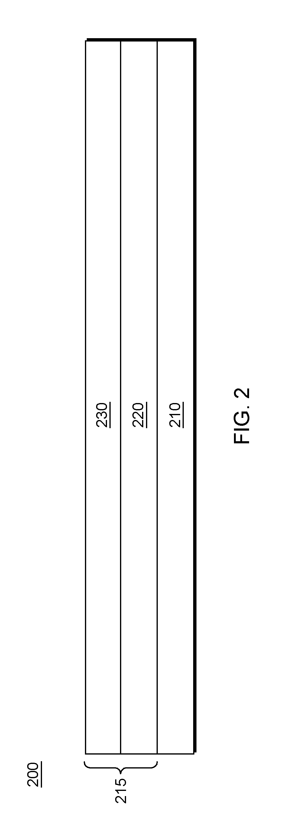
FIELD OF THE INVENTION[0001]The present invention relates to methods of analyzing the bandgap of a high-k metal gate, and more particularly, to better modeling of the bandgap to determine electrical parameters.BACKGROUND[0002]For complementary metal-oxide-semiconductor (CMOS) devices at or below 45 nm, equivalent oxide thickness (EOT) scaling and control has become critical, especially with the use of high-k / metal gate (HKMG) technology. In particular, a dielectric with higher dielectric constant than SiO2 and metal gate are used, with some material selection and combinations for work function tuning necessary. To further scale the EOT of HKMG, nitridation to the interfacial layer and / or high-k dielectric are often introduced, with nitridation possible. However, control of the leakage current of the high-k gate stack is important, which is determined frequently by the elemental profile (such as nitrogen) and composition of the layers of the device. There is a great challenge in link...

Claims


Application Information

Patent Timeline
IPC IPC(8): G01R31/265H01L21/66H01L21/28G01R31/02G01R31/26G01B15/02G01N21/21G01N21/33G01N33/00
CPCG01R31/2656H01L22/12H01L21/28202H01L21/28185G01R31/025G01R31/2601G01B15/02G01N21/211G01N21/33G01N33/00H01L29/42364H01L29/517H01L29/518G01N2021/213G01N2033/0095G01N2021/335G01N21/8422H01L22/14G01B11/0641G01N33/0095
Inventor DAI, MINSCHEPIS, DOMINICZHAO, QIANGDI, MINGHU, DAWEI
Owner GLOBALFOUNDRIES US INC
Learn More