Rechargeable electrochemical lithium ion cell

a lithium ion battery and electrochemical technology, applied in secondary cells, electrochemical generators, cell components, etc., can solve the problems of poor electrolyte conductivity, poor performance of lithium ion rechargeable cells at low temperatures, and sluggish charge transfer kinetics, etc., to achieve high energy density and high performance.

Inactive Publication Date: 2019-08-22
FARMAKIS FILIPPOS +5
View PDF0 Cites 0 Cited by
  • Summary
  • Abstract
  • Description
  • Claims
  • Application Information

AI Technical Summary

Benefits of technology

[0012]The advantages presented by the present disclosure in comparison with the state-of-the-art technologies is the high cell energy density (>200 Wh / kg) along with the capability of the cells to be efficiently charged at low temperatures (at least −40° C.) delivering capacity more than 70% than the capacity provided at room temperature.

Problems solved by technology

It is generally believed that the poor performance of lithium ion rechargeable cells at low temperatures are associated with: poor electrolyte conductivity, sluggish kinetics of charge transfer, increased resistance of solid electrolyte interphase, and slow lithium ion diffusion through the surface atomic layers and through the bulk of electrodes' active material particles.
Even though the cells were discharged at low temperature, they were always charged at room temperature which limited the opportunities of exploitation of such cells.
Moreover, in these cells the charging-discharging cycles were not performed entirely in the desired operating temperature (−30° C.) since charging was done at room temperature.
This specific condition during charging is the main drawback of the proposed solutions since it necessitates the cell heat-up at room temperature (commonly with the aid of resistors) and thus the consumption of a large amount of energy during cell charging.
This energy consumption during charging restricts the use of lithium-ion cells especially at applications where the available charging energy is limited while at the same time increases the total system cost.

Method used


Image

  • Rechargeable electrochemical lithium ion cell
  • Rechargeable electrochemical lithium ion cell
  • Rechargeable electrochemical lithium ion cell

Examples


Embodiment Construction

[0018]An application example of the present disclosure is presented with detailed description and references to the attached drawings.

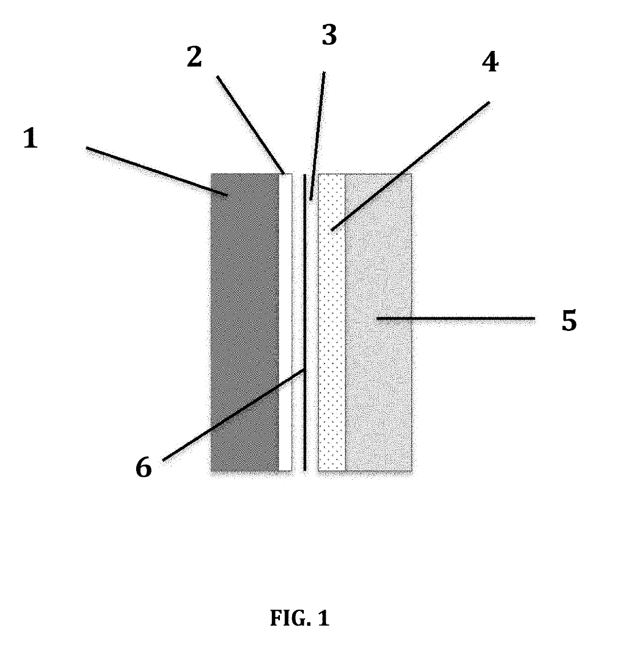
[0019]As shown in FIG. 1, an electrochemical lithium ion cell is comprised of the following elements:

[0020]At least one thin metal foil (1) that serves as current collector for the anode. The thin metal foil (1) can be made either from copper or other metal.

[0021]Microcrystalline or amorphous silicon film (2) formed in granular and / or columnar structure which has been deposited at least on one of the two sides of the thin metal foil (1) by techniques such as Physical Vapor Deposition (PVD), Chemical Vapor Deposition (CVD), spin coating, spray pyrolysis or others similar techniques. The anode material (2) should provide a high active surface with high specific capacity in lithium, higher than 1500 mAh / g.

[0022]Electrolyte (3) consisting of lithium hexafluorophosphate (LiPF6) in a non-aqueous organic solvent. The non-aqueous organic solvent is composed o...


PUM

PropertyMeasurementUnit
temperaturesaaaaaaaaaa
temperature capacityaaaaaaaaaa

Abstract

A rechargeable electrochemical lithium-ion cell for energy storage combines active materials (anode, cathode, electrolyte) in a way that it can operate with high energy density (>200 Wh / kg) and high performance during charging and discharging at a wide temperature range and more specifically at temperatures lower than −20° C. and at least as low as −40° C. The present disclosure facilitates the development of systems and devices requiring high energy density storage systems and thus low weight and operation at low temperature conditions with low energy consumption. The present disclosure can be applied to space technology, military applications as well as in the automotive industry where interest is focused on low weight batteries being capable to operate efficiently at low temperatures.

Description

BACKGROUNDTechnical Field[0001]The present disclosure belongs to the field of electrochemical energy storage and more precisely to rechargeable lithium-ion batteries.Description of the Related Art[0002]It is generally believed that the poor performance of lithium ion rechargeable cells at low temperatures are associated with: poor electrolyte conductivity, sluggish kinetics of charge transfer, increased resistance of solid electrolyte interphase, and slow lithium ion diffusion through the surface atomic layers and through the bulk of electrodes' active material particles. In order to solve this issue, two solutions have been proposed in the current state of the art: (i) to modify interfacial properties to reduce the high activation energy of charge-transfer kinetics, by surface coating or changing electrolyte composition and (ii) to increase interfacial area by using nanostructured electrodes or electrodes of different morphology. Additionally, major attention is given in the operat...

Claims


Application Information

Patent Timeline
Patent Type & Authority Applications(United States)
IPC IPC(8): H01M10/0569H01M4/58H01M10/0525H01M4/38H01M4/505H01M4/525H01M10/0568H01M10/0567H01M10/42
CPCH01M10/0569H01M4/5825H01M10/0525H01M4/386H01M4/505H01M4/525H01M10/0568H01M10/0567H01M10/4235H01M2004/021H01M2300/004H01M4/134H01M4/1391H01M4/485Y02E60/10H01M4/13H01M10/052H01M10/0564
Inventor FARMAKIS, FILIPPOSELMASIDIS, KONSTANTINOSGEORGOULAS, NIKOLAOSTSIPLAKIDIS, DIMITRIOSBALOMENOU, STYLIANINESTORIDI, MARIA
Owner FARMAKIS FILIPPOS
Why Eureka
Try Eureka