Device for Processing Scrap Rubber

a technology for scrap rubber and rubber slag, which is applied in the direction of gasification process details, special form destructive distillation, tyres, etc., can solve the problems of carbon surface oxidation, quality degradation, etc., and achieves the reduction of liquid fuel consumption, the effect of improving solid residue quality, and avoiding the loss of valuable liquid products

Active Publication Date: 2019-08-29
SUSEKOV SERGEI PAVLOVICH
View PDF0 Cites 4 Cited by
  • Summary
  • Abstract
  • Description
  • Claims
  • Application Information

AI Technical Summary

Benefits of technology

[0046]Some of the hydrocarbon vapors having a low boiling point (below 100° C.) are not condensed in the condenser. To prevent emission of non-condensable hydrocarbon vapors to the environment, the condenser's gas outlet is connected to the heating pipes. Thus, non-condensable hydrocarbon vapors are supplied to the heating pipes and burnt, which enables beneficial use of the vapor energy and a reduction of the liquid fuel consumption for the recycling process.
[0047]The solid residue generated in the rubber waste processing has a high ash content (about 12-14% wt., depending on the rubber waste type) and therefore cannot be used for the manufacturing of critical rubber articles. Theref...

Problems solved by technology

1. Incomplete extraction of liquid fraction (oil) from the gas flow, as a result losing some valuable liquid products. This is caused by air-washing the produced carbon black with adsorbed oil, the cord fabric being completely burnt, some of the oils burnt, and some carried away with flue gases.
2. Low quality of carbon black due to oil adsorption, so that to remove some of the oil, carbon black is air-washed; as a result, the carbon surface oxidizes and its quality deteriorates.
3. High energy consumption of the process dictated by the necessity to use a circulating heat transfer agent, which has to be separated from hydrocarbon vapors generated in thermal decomposition of rubber, then to be heated in a heat exchanger, evaporated, and superheated in a furnace prior to feeding to the reactor.
1. Incomplete extraction of the liquid fraction (oil) from the gas flow, resulting in the loss (burning in the heating chamber burners) of a part of valuable liquid products, with high pollutant emission to the environment due to inability to provide complete burning of pyrolysis gases with a high resin content in the heating chamber burners.
2. Low quality of solid pyrolysis products due to residual hydrocarbons (volatile products), which cannot be separated in the process of drying, therefore additional thermal treatment of the said products is necessary at a high temperature of about 800° C.
3. High energy consumption of the process due to heat losses in the process and the need to increase the temperature in the furnace to 800° C.
1. Incomplete extraction by the condensers of the liquid fraction (oil) from the gaseous products of worn tire...

Method used


Image

  • Device for Processing Scrap Rubber
  • Device for Processing Scrap Rubber
  • Device for Processing Scrap Rubber

Examples


example 1

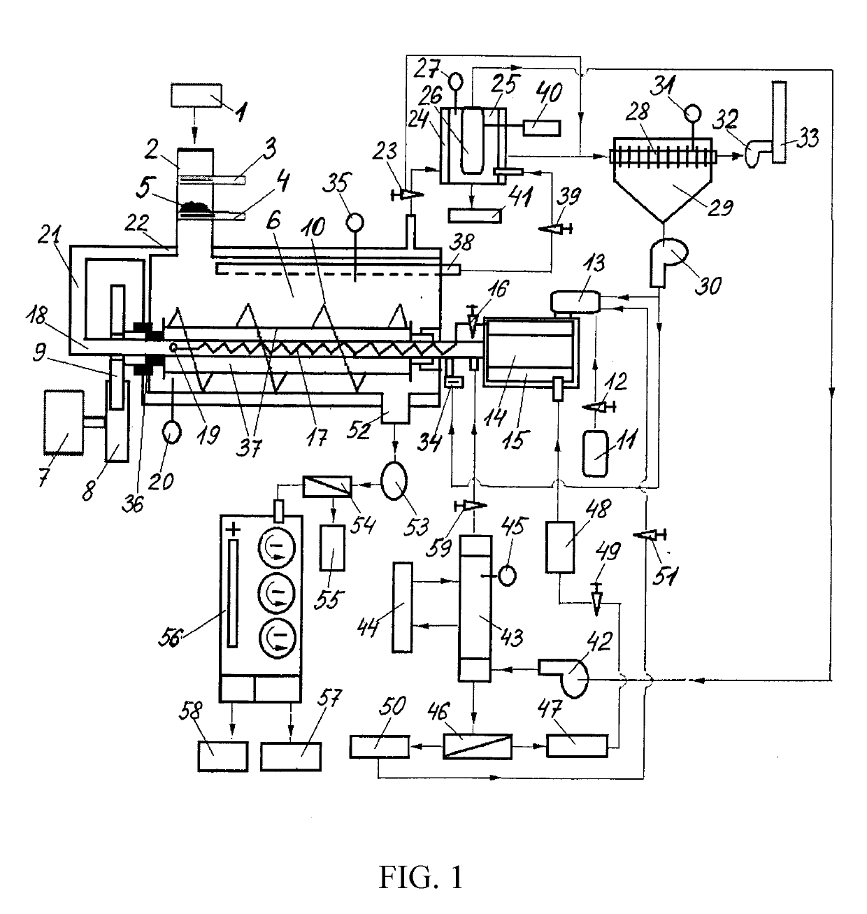
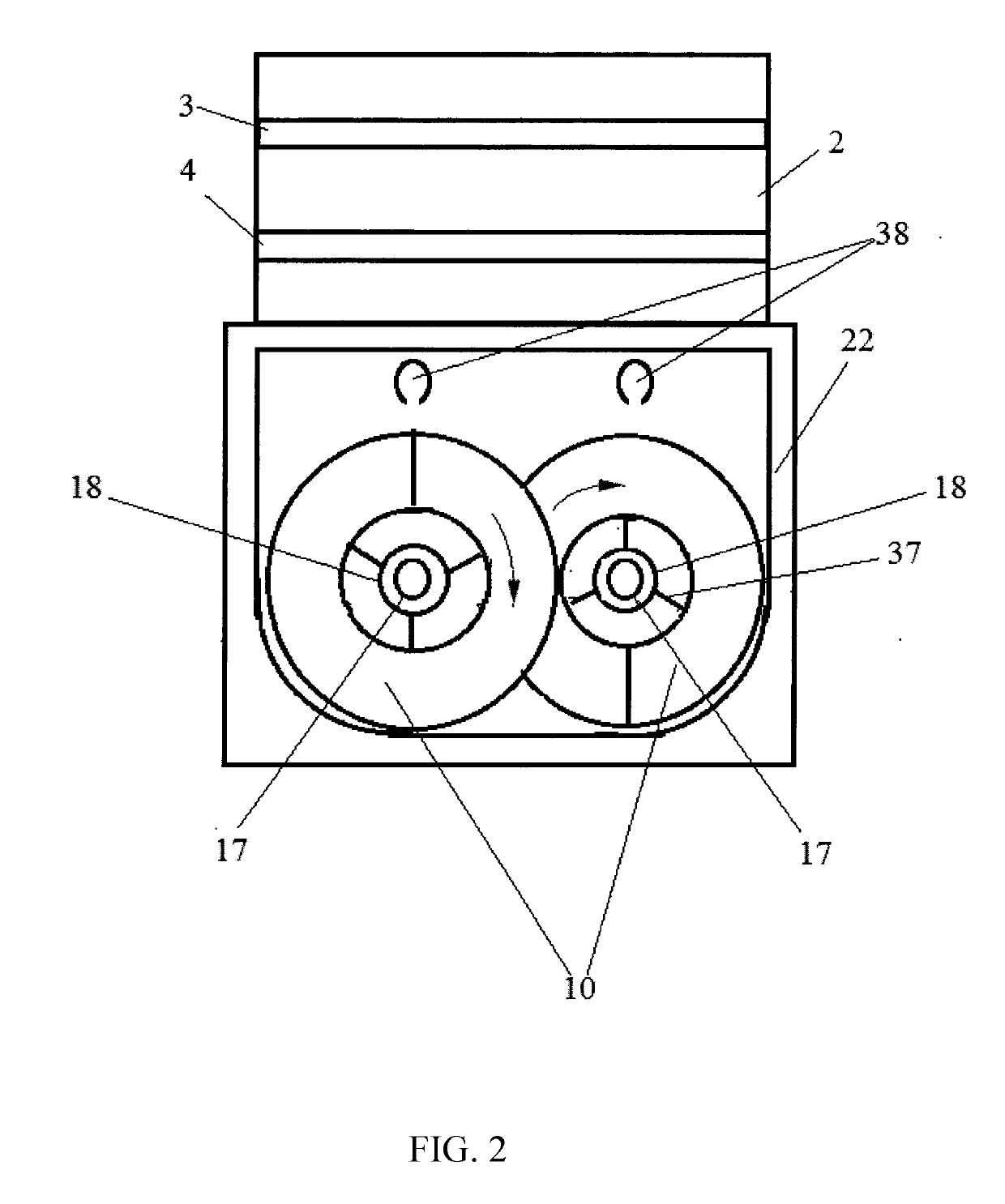
[0083]Shredded rubber waste 5 in the form of chips is fed from storage 1 to bin 2 with gates 3 and 4 closed, at the rate of 100 kg every 6 minutes. The dimensions of the rubber chips are: length l=50 mm, width s=50 mm, and height h=30 mm. In this case, the total flow rate of waste is Go=1000 kg / h. When bin 2 has been filled, gate 3 is opened, and waste in the quantity of 100 kg from bin 2 pours down and is checked by gate 4. After this, gate 3 is closed, gate 4 is opened, and waste pours down to reactor 6 and is uniformly distributed, 50 kg to each section of the reactor. Next, gate 4 is closed. Thus, waste is loaded to reactor 6 batch-wise every 6 minutes.

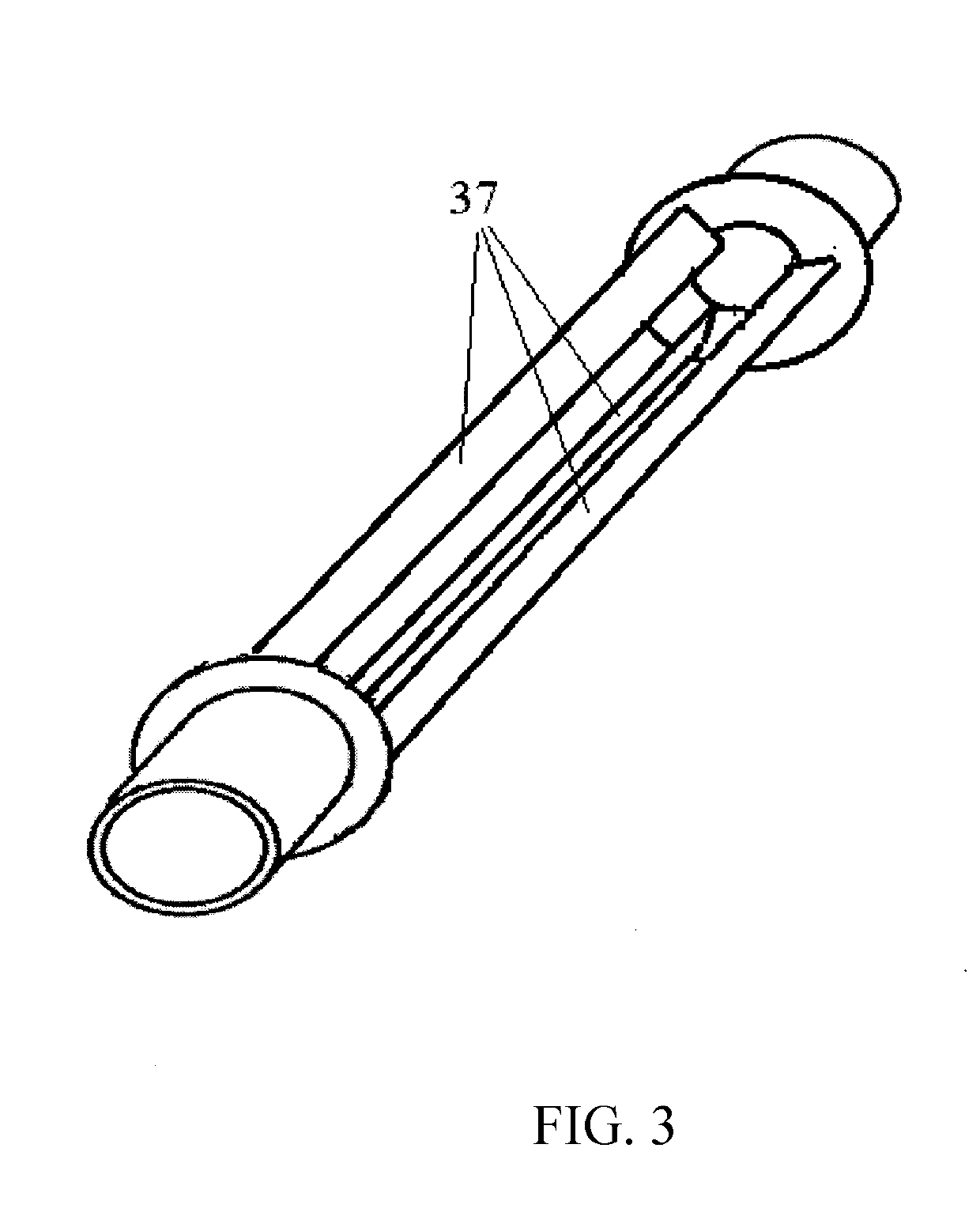
[0084]Simultaneous with the loading of the first batch of waste, gear 8 is set in motion by motor 7 at the speed of 2 rpm. Gear 8 engages first gear 9 connected to first screw 10 and second gear 9 connected to second screw 10. Such connection of the gears with gear 8 in rotation results in screws 10 rotating towards each other. Si...

example 2

[0141]Shredded rubber waste 5 in the form of chips is fed from storage 1 to bin 2 with gates 3 and 4 closed, at the rate of 150 kg every 6 minutes. The dimensions of the rubber chips are: length l=30 mm, width s=50 mm, and height h=20 mm. In this case, the total flow rate of waste is Go=1500 kg / h. When bin 2 has been filled, gate 3 is opened, and waste in the quantity of 150 kg from bin 2 pours down and is checked by gate 4. After this, gate 3 is closed, gate 4 is opened, and waste pours down to reactor 6 and is uniformly distributed, 75 kg to each section of the reactor. Next, gate 4 is closed. Thus, waste is loaded to reactor 6 batch-wise every 6 minutes.

[0142]Simultaneous with the loading of the first batch of waste, gear 8 is set in motion by motor 7 at the speed of 3 rpm. Gear 8 engages first gear 9 connected to first screw 10 and second gear 9 connected to second screw 10. Such connection of the gears with gear 8 in rotation results in screws 10 rotating towards each other. Si...


PUM


Abstract

A device for processing scrap rubber has a reactor with a screw conveyor disposed inside a heating chamber, a thermal decomposition unit, burners, a condenser, a cyclone filter, and devices for discharging solid residue and removing a gas-vapor mixture. The reactor has two sections connected in parallel. The thermal decomposition unit has screw conveyors in each section, the conveyors have axial heating pipes with a coil. Along the length of the conveyors plates are arranged at the corners of an equilateral triangle in contact with and perpendicular to the side surface of the heating tube. A cylinder furnace with an evaporator and a burner is connected to the ends of the pipes. An outlet of the condenser is connected to a liquid fraction separator, inlets of the coils are connected to an outlet of the evaporator, and an inlet of the evaporator is connected to an outlet from the separator.

Description

RELATED APPLICATIONS[0001]This Application is a Continuation application of International Application PCT / RU2017 / 000832, filed on Nov. 7, 2017, which in turn claims priority to Russian Patent Application RU2016146652, filed Nov. 28, 2016, both of which are incorporated herein by reference in their entirety.FIELD OF THE INVENTION[0002]The invention relates to waste recycling technologies and may be applied in the rubber industry, chemical industry, fuel and energy sector, and in the housing and public utility sector to produce fuel and raw material resources from waste.BACKGROUND OF THE INVENTION[0003]There is a known process and plant for rubber-containing waste recycling (RU Patent No. 2460743, IPC C08J11 / 20, published 10 Sep. 2012).[0004]The plant for processing rubber-containing waste comprises a reactor, a filter, heat exchange equipment, and separation equipment. The reactor consists of two sections: crumb rubber thermolysis section and carbon black marketable conditioning sect...

Claims


Application Information

Patent Timeline
IPC IPC(8): C10G1/10C08J11/20B29B17/02C10B53/07
CPCC10G1/10C08J11/20B29B2017/0272C10G2300/1003B29B17/02C10B53/07B29B17/04B29B2017/0496B29L2030/00C10B47/44C10B57/18C10J3/007C10J2300/0946C10J2300/0976C10J2300/1246C10J2300/1687C10J2300/1853C10K1/026C10K1/04Y02W30/52Y02W30/62Y02P20/143B29B17/00C08J11/00
Inventor GRADOV, ALEKSEI S.SUSEKOV, EVGENY S.SUSEKOV, SERGEI P.
Owner SUSEKOV SERGEI PAVLOVICH
Why Eureka
Try Eureka