Methods and apparatus to separate biological entities

Pending Publication Date: 2019-09-05
APPL CELLS INC
View PDF0 Cites 0 Cited by
  • Summary
  • Abstract
  • Description
  • Claims
  • Application Information

AI Technical Summary

Benefits of technology

[0017]This invention describes novel methods and novel magnetic separation devices (“MAG”) that are able to: (1) separate biological entities bound with SPL from biological solution with high flow rate, without exposure of biol

Problems solved by technology

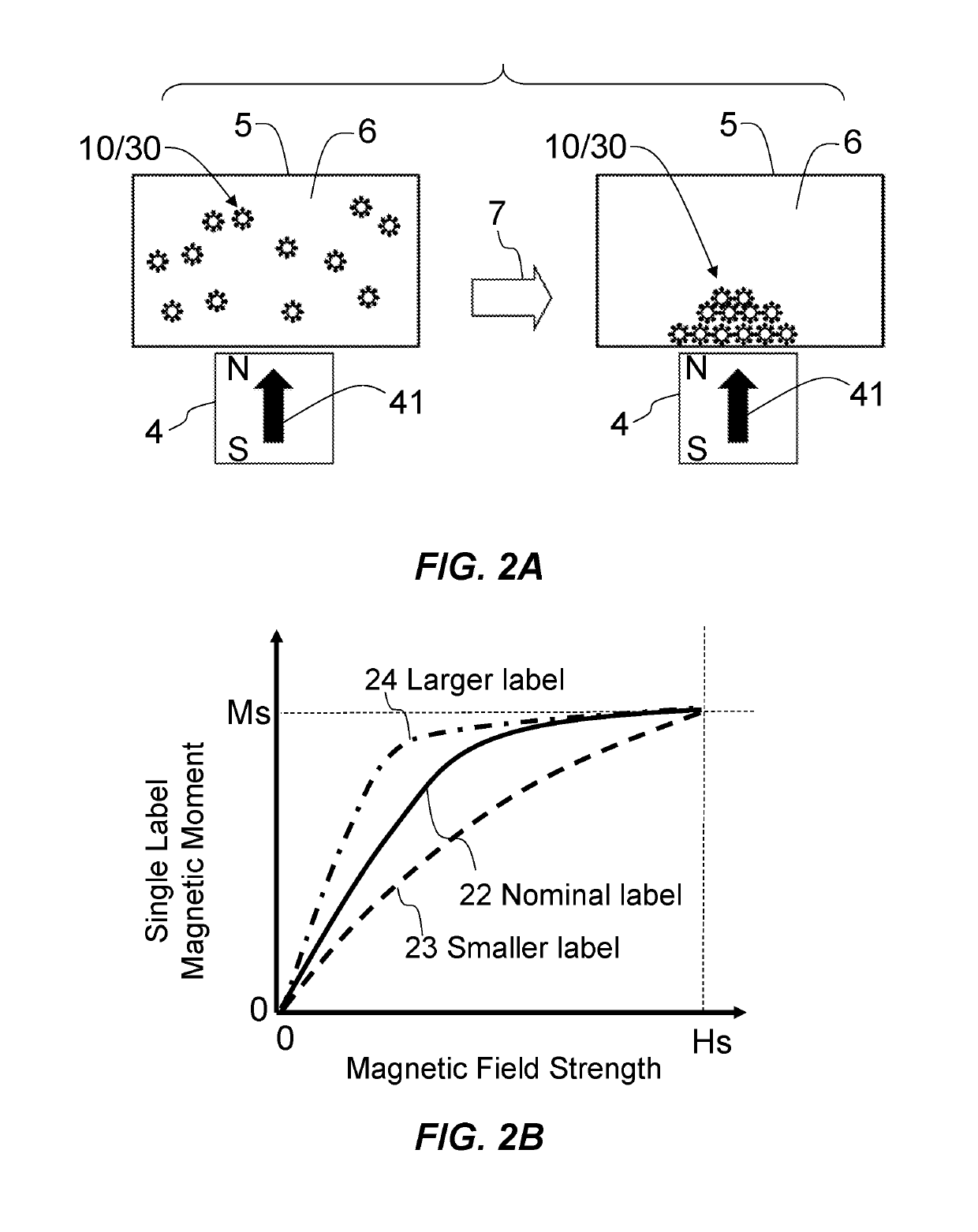
Conventional method as shown in FIG. 2A has limitations in actual applications.
Besides overall process being slow, another drawback in conventional method of FIG. 2A is that the operation as described in FIG. 2A typically involves air exposure of cells 10/30 conglomerate during the steps of solution removal and later removal of cells 10/30 from container 5.
Such air exposure poses challenge in achieving sterile separation of cells 10/30 for clinical purpose, as well as risk of cell 10/30 damage or death that negatively affects further cellular processes of cell 10/30.
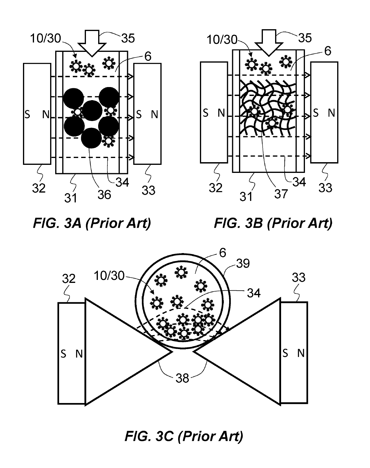
However, such forced flow will inevitably causes mechanical damage to the cells and will still leave significant percentage of cells 10/30 in column 31 due to the strong domain wall field of spheres 36.
Besides cells 10/30 loss, another intrinsic issue of FIG. 3A method is introducing spheres 36 as foreign materials in the flow of solution 6, which is not desirable for sterile process needed for clinical applications.
However, prior art of FIG. 3C also has intrinsic deficiencies.
First deficiency is the flow speed of solution 6, or flow rate, in the tubing 39 is limited by the prior art design of FIG. 3C.
The separation speed of cells 10/30 of prior art as in FIG.

Method used


Image

  • Methods and apparatus to separate biological entities
  • Methods and apparatus to separate biological entities
  • Methods and apparatus to separate biological entities

Examples


Example

[0191]FIG. 4 shows a cross-sectional view of the first embodiment of a magnetic separation device (“MAG”) of the current invention. MAG 121 is composed of two magnetic field producing poles, pole 102 and pole 103. Each of the poles 102 and 103 is composed of soft magnetic material, which may include one or more elements of iron (Fe), cobalt (Co), nickel (Ni), iridium (Ir), manganese (Mn), neodymium (Nd), boron (B), samarium (Sm), aluminum (Al). Pole 102 has a magnetic flux collection end 1023 and a tip end 1021, where shape of the pole 102 is converging from the flux collection end 1023 towards the tip end 1021. In FIG. 4, flux collection end 1023 is a flat surface which is contacting, or in proximity to, the North Pole (“N”) surface of a permanent magnet 104. Permanent magnet 104 has a magnetization as shown by arrow 1041 in FIG. 4 which points from the South Pole (“S”) surface of to the N surface of the magnet 104. Magnetization 1041 produces magnetic field in free space, which ca...

Example

[0198]FIG. 8A is a cross-sectional view of a second embodiment of MAG of current invention. MAG 122 in FIG. 8A is substantially similar as MAG 121, except a soft magnetic shield 106 is attached to the S surface of magnetic 104 and N surface of magnet 105. Magnetic flux from S surface of magnet 104 and N surface of magnet 105 forms closure path within the soft magnetic shield 106. MAG 122 compared to MAG 121 will have less magnetic flux leakage outside of the MAG 122 structure, where magnetic flux generated by magnets 104 and 105 are mainly confined within the soft magnetic material body of poles 102 and 103, and shield 106. MAG 122 is preferred in applications where magnetic interference from MAG 122 to other surrounding instrument or equipment is desired to be minimized.

Example

[0199]FIG. 8B is a cross-sectional view of a third embodiment of MAG of current invention. Compared to MAG 121, MAG 123 of FIG. 8B incorporates only one permanent magnet 108, which is attached to both poles 102 and 103, where flux from N surface of magnet 108 and flux from S surface of magnetic 108 is conducted by poles 102 and 103 to produce MAG 123 gap field by tip ends 1021 and 1031. Compared to MAG 121, magnetic flux generated by magnet 108 is mainly confined within the soft magnetic material body of poles 102 and 103, and MAG 123 is comparatively easier to assemble and produces less magnetic flux leakage.

[0200]FIG. 9 shows a cross-sectional view of the first embodiment MAG 121 being used for magnetic separation in combination with a flexible channel 201. FIG. 9 is similar to FIG. 4, except that the rigid channel 101 is replaced with a flexible channel 201. Flexible channel 201 may assume any shape, including a circular shape tubing form, at its non-deformed state, but can be de...


PUM

PropertyMeasurementUnit
Forceaaaaaaaaaa
Flow rateaaaaaaaaaa
Sizeaaaaaaaaaa

Abstract

The current invention relates to the method and apparatus to separate biological entities from a fluid sample. The claimed methods separate biological entities based on size of entities by using acoustic pressure nodes in a microfluidic device. The claimed methods further separate biological entities with magnetic labels and by using a magnetic device. The claimed methods further include combination of microfluidic devices and magnetic devices to separate biological entities from a fluid sample.

Description

BACKGROUND[0001]The current invention generally relates to methods and apparatus to separate biological entities, including cells, bacteria and molecules from human blood, body tissue, body fluid and other human related biological samples. The disclosed methods and apparatus may also be utilized to separate biological entities from animal and plant samples. More particularly, the current invention relates to the methods and apparatus for achieving separation of biological entities with using one or more of a micro-fluidic separation device / chip (“UFL”), and one or more of a magnetic separation device (“MAG”), individually or in combination. For description purpose, “cells” will be used predominantly hereafter as a typical representation of biological entities in general. However, it is understood that the methods and apparatus as disclosed in this invention may be readily applied to other biological entities without limitation.[0002]Separation of biological entities from a fluid bas...

Claims


Application Information

Patent Timeline
IPC IPC(8): B01L3/00G01N33/49G01N1/40B03C1/033B03C1/28B03C1/30
CPCB01L3/502753B03C2201/26G01N1/4077B01L3/50273B01L3/502715B03C1/0332B03C1/288B03C1/30B01L2200/027B01L2200/0647B01L2400/043B01L2400/0496B01L2400/0457B01L2400/0487B01L2300/021B03C2201/18G01N33/491C12M47/04C12M23/16C12M47/06C12N15/1003C12N5/00C12N2509/10B01L3/502761B01L2200/0652B01L2300/0864B01L2400/0436B01L2400/0439G01N27/745B03C1/01G01N15/1459G01N2015/149G01N2015/1006G01N2015/1486B01D21/283B01L2300/0861B01L2200/0668G01N33/54326G01N33/54333G01N35/0098G01N2035/00554A61K38/27C12Q1/6806B03C1/005B01D35/06B03C2201/20B03C1/23G01N15/00B01F31/86
Inventor ZHOU, YUCHEN
Owner APPL CELLS INC
Why Eureka
Try Eureka