
Feedstock for an additive manufacturing method, additive manufacturing method using the same, and article obtained therefrom

a technology of additive manufacturing and additive manufacturing method, applied in the directions of additive manufacturing process, manufacturing tool, transportation and packaging, etc., can solve the problems of large machinery, time-consuming, and less suitable for preparing customized articles in a short tim

Active Publication Date: 2019-10-10
HOGANAS AB
View PDF0 Cites 5 Cited by
  • Summary
  • Abstract
  • Description
  • Claims
  • Application Information

AI Technical Summary

Benefits of technology

The patent aims to provide a feedstock for 3D printing that has a high concentration of sinterable particles and produces a final product with low shrinkage. Additionally, the invention aims to create a sintered body with strong and dense structural parts that reach at least 65% of the density of the bulk material.

Problems solved by technology

These methods are however complex, require large machinery and are time consuming, and are thus generally more suitable to produce mass-produced articles and less suitable to prepare customized articles in a short time.
Additive manufacturing methods thus continue where conventional manufacturing methods fail to deliver.
These processes however require a large amount of metal powder that is subsequently discarded or needs to be recycled.
However, all-thermoplastic materials do have certain drawbacks.
The manufactured object is generally not stable under high temperature, does not have high strength, and the optical appearance is often not satisfactory.
Due to their inherent brittleness, such materials are however are not extrudable.
A drawback is however then the need to remove the binder system and to fuse the particles, typically by heat treatment, to form the desired object.
Developing a feedstock and binder system that is suitable, in particular for an FFF method, and that also satisfies most or all of the above criteria is challenging and has not been achieved so far.
This makes a proper handling by end customers more difficult or prevents a smooth automatic printing process without the need for manual feedstock feeding operations.
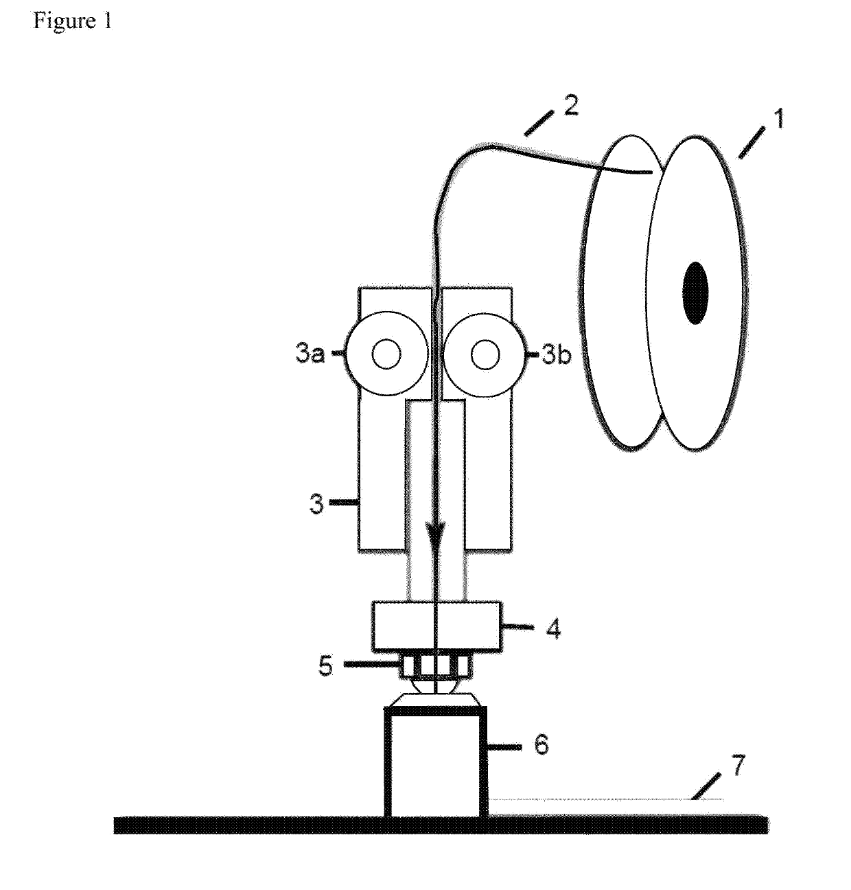
Such feedstocks can hence not be sold to end customers using commercially available FFF equipment, such as the FlashForge Dreamer™ 3D printer.
Further, many currently developed feedstocks have a low loading of sinterable particles and thus suffer severe shrinkage (and possibly also distortion) during the subsequent debinding and sintering steps.

Method used


Image

  • Feedstock for an additive manufacturing method, additive manufacturing method using the same, and article obtained therefrom
  • Feedstock for an additive manufacturing method, additive manufacturing method using the same, and article obtained therefrom
  • Feedstock for an additive manufacturing method, additive manufacturing method using the same, and article obtained therefrom

Examples


examples 1 to 10

and Feedstocks F1 to F10

I. Filament Feedstocks

[0161]The following filament feedstocks F were made by mixing the respective components in their respective amounts given in Table 1 below:

TABLE 1Exemplary Feedstock CompositionsComp.P:SSKurarityPowderLB550KurarityKurarityFusabond[wt. %[wt. % ofLA4285LA2140P353ofbinder[wt. % of[wt. % of[wt. % ofFeed-totalcom-binderbinderbinderstockfeedstock]position]composition]composition]composition]F188.4492——8F289.42——928F389.11—92—8F489.21—64288F589.27—46468F689.33—28648F787.7394——6F887.9190——10F987.9988——12F1088.0886——14

[0162]Herein, the compounds were as follows:

Sinterable Particles (P):

[0163]17-4 PH stainless steel, water atomized and sieved to a particle size of <45 μm. The water atomizing process yields particles of irregular shape, which would not likely be easily 3D printed because of its poor flow properties compared to spherical powders. However, the debinding step after printing could be assisted by the irregular shape since all of the int...

examples 1a and 1b

Filament Production Using Feedstock F1

example 1a

in the Göttfert MI-2 Melt Indexer

[0175]A filament could be successfully obtained by setting the temperature to 210° C. The filament was continuous, flexible and had a good surface finish.


PUM

PropertyMeasurementUnit
Tgaaaaaaaaaa
Tgaaaaaaaaaa
diameteraaaaaaaaaa

Abstract

A feedstock for a 3D manufacturing process, in particular a Fused Filament Fabrication process. The feedstock includes (P) sinterable particles made of a metal, metal alloy, glass, ceramic material, or a mixture thereof; and (B) a binder composition including (b1) 5-15% by weight, relative to the total weight of the binder composition, of a polymeric compatibilizer, and (b2) 85-95% by weight, relative to the total weight of the binder composition, of a polymeric binder component, the polymeric binder component being selected from the group consisting of (b2-1) a polymer mixture or polymer alloy, the mixture or alloy including at least a first and a second polymer; (b2-2) one, two or more block copolymers, including at least a first polymer block and second polymer block; and (b2-3) mixtures of (b2-1) and (b2-2), wherein the amount of sinterable particles P is 40 Vol % or more of the composition.

Description

DESCRIPTION OF RELATED ART[0001]Conventionally, parts made of solid and hard materials, such as metals, steels or ceramics, have been produced by subtractive manufacturing processes, e.g. machining. Specific shapes have been realized by cold and hot working processing methods, e.g. forging. These methods are however complex, require large machinery and are time consuming, and are thus generally more suitable to produce mass-produced articles and less suitable to prepare customized articles in a short time.[0002]In the area of customized articles, rapid prototyping / rapid manufacturing has been developed. This area is of growing interest for many applications, as customized articles can be produced by computer-assisted equipment, such as laser cutting, laser sintering, etc. Rapid prototyping and rapid manufacturing is realized in a number of ways, including additive and subtractive techniques.[0003]In recent years, various additive manufacturing processes have come to light. These pro...

Claims


Application Information

Patent Timeline
Patent Type & Authority Applications(United States)
IPC IPC(8): B22F3/00B29C64/165B29C64/218B22F1/103
CPCB33Y30/00B29C64/218B22F2998/10B22F2001/0066B33Y10/00B29C64/165B22F3/1021C04B2235/6026B22F3/008B33Y70/00B22F1/103B22F10/32B22F10/18B22F3/105B29C70/00B33Y70/10B33Y80/00B29C64/10B29C64/118B22F10/10
Inventor LUNDIN, EVADARNIS, MAGALIENILSSON, SOFIAFLODIN, ANDERS
Owner HOGANAS AB
Learn More