
Silanated Silica-Ceramic Materials, and Methods of Making and Using the Same

a technology of silica-ceramic materials and silica-ceramic materials, which is applied in the direction of cell components, cell component details, electrochemical generators, etc., can solve the problems of physical and electrochemical problems, severe damage, injury or death, poor adhesion to or compatibility with lithium metal,

Active Publication Date: 2019-10-17
TEMPLE UNIVERSITY
View PDF2 Cites 7 Cited by
  • Summary
  • Abstract
  • Description
  • Claims
  • Application Information

AI Technical Summary

Benefits of technology

The invention relates to a composite material made of ceramic, metal oxide, and a coupling agent, where the coupling agent is covalently bonded to the metal oxide. The ceramic can be Li2O, Al2O3, SiO2, P2O5, TiO2, or GeO2. The metal oxide can be silica or alumina. The coupling agent can be a silane, carboxylic acid, carboxylate, or organic coupling agent. The composite material can be in the form of particles or a membrane. The conductivity of the composite material is about 1.5×10⁻⁴ S / cm at 30°C. The composite material can be used in a battery separator or a membrane. The invention also includes a method for making the composite material and a method for using it in a battery.

Problems solved by technology

There is a strong drive for safer lithium ion batteries, as current technology relies upon flammable liquid electrolytes, which occasionally cause LIBs to ignite or explode, causing severe damage, injury, or death.
Ceramic electrolytes have high ionic conductivity (σ) and lithium ion transference numbers (tLi+→1), the fraction of the charge carried by the Li+, making them single ion conductors (SICs), but are brittle, with poor adhesion to or compatibility with lithium metal (Li0).
This technology exhibits good ionic and lithium ion transference numbers of unity, but has major physical and electrochemical issues with its use.
Beyond the physical abuse lithium ion batteries are subjected to in use, e.g. shock and vibration in the automotive industry, the battery components (e.g. in the cathodes) physically change shape during charging / discharging as a result of the chemical reactions taking place in the active electrode components, delaminating the LICGC from the electrodes, and resulting in capacity losses.
In the case of Li0(or Na0), the ceramics often continually react with the metal, causing the cell to short.
These limitations prevent ceramics from being competitive with existing liquid electrolytes.
However, polymer electrolytes have low ionic conductivity [Ling et al., 2006, Prog. Chem., 18, (4), 459-466; Dias et al., 2000, Journal of Power Sources, 88, (2), 169-191], and poor resistance to dendrite growth [Kalnaus et al., 2011, Solid State Ionics, 199, 44-53; Kalnaus et al., 2012, Journal of Power Sources, 201, 280-287].
These are serious hindrances to their adoption for use in commercial batteries as batteries produced with polymer electrolytes will have significantly less power than existing technologies.
Despite extensive research on ceramic and polymer separators, no effective solutions have been reported to solve their major drawbacks.
What has stymied the development of hybrid LICGC-polymer solid electrolytes is the inability to successfully control the interface between the two materials.
However, without the addition of LiX, these polymers are insulators and the composite conductivity typically decreases.
The published results strongly suggest that the problem with hybrid ceramic / polymer separators resides in the interfacial region.

Method used


Image

  • Silanated Silica-Ceramic Materials, and Methods of Making and Using the Same
  • Silanated Silica-Ceramic Materials, and Methods of Making and Using the Same
  • Silanated Silica-Ceramic Materials, and Methods of Making and Using the Same

Examples


experimental examples

[0053]The invention is further described in detail by reference to the following experimental examples. These examples are provided for purposes of illustration only, and are not intended to be limiting unless otherwise specified. Thus, the invention should in no way be construed as being limited to the following examples, but rather, should be construed to encompass any and all variations which become evident as a result of the teaching provided herein.

[0054]Without further description, it is believed that one of ordinary skill in the art can, using the preceding description and the following illustrative examples, make and utilize the compositions of the present invention and practice the claimed methods. The following working examples therefore, specifically point out the preferred embodiments of the present invention, and are not to be construed as limiting in any way the remainder of the disclosure.

example 1

olymer Interface

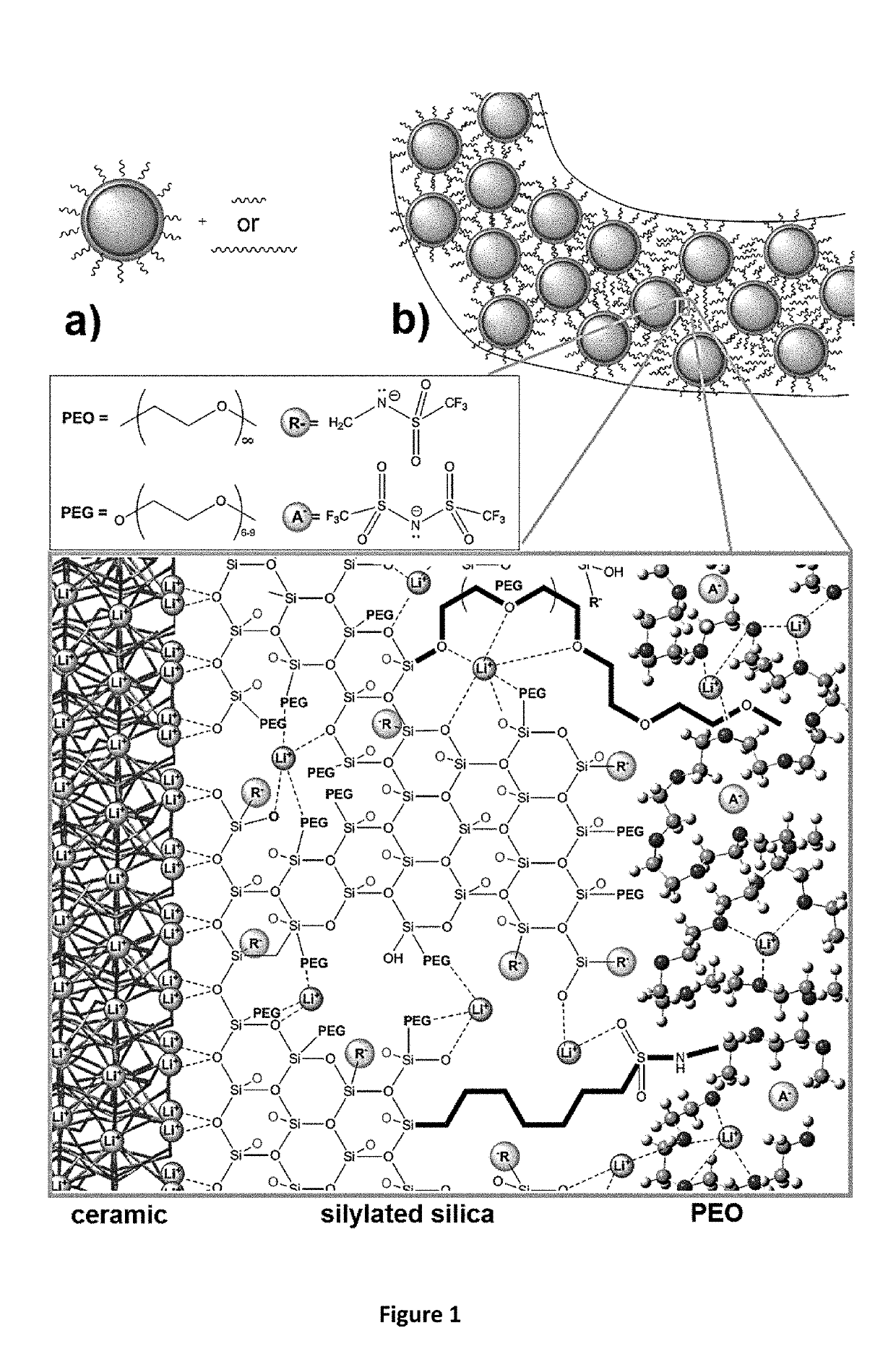
[0055]In order to ensure high power density and protect LICGCs from Li0 metal, the interface created between the ceramic and the polymer must have a low interfacial resistance, be able to prevent Li0(or Na0) corrosion of the LICGC, and adhere to the polymer. The interface and / or the polymer connected to the interface should be stable with respect to Li0 or Na0. Since solid electrolyte interfaces (SEIs) are expected to be formed during charging, an SEI that prevents continual corrosion of the Li, and which has good ionic conductivity and poor electrical conductivity needs to be formed. These SEIs have been shown to form on PEO-type polymers, particularly with added SiO2 [Croce et al., 2001, Electrochimica Acta, 46, (16), 2457-2461; Persi et al., 2002, Journal of the Electrochemical Society, 149, (2), A212-A216], and continual corrosion is prevented since there is very slow diffusion of the formed chemical products through the solid polymer electrolyte.

[0056]In order t...

example 2

Silica Ceramic Conductivity

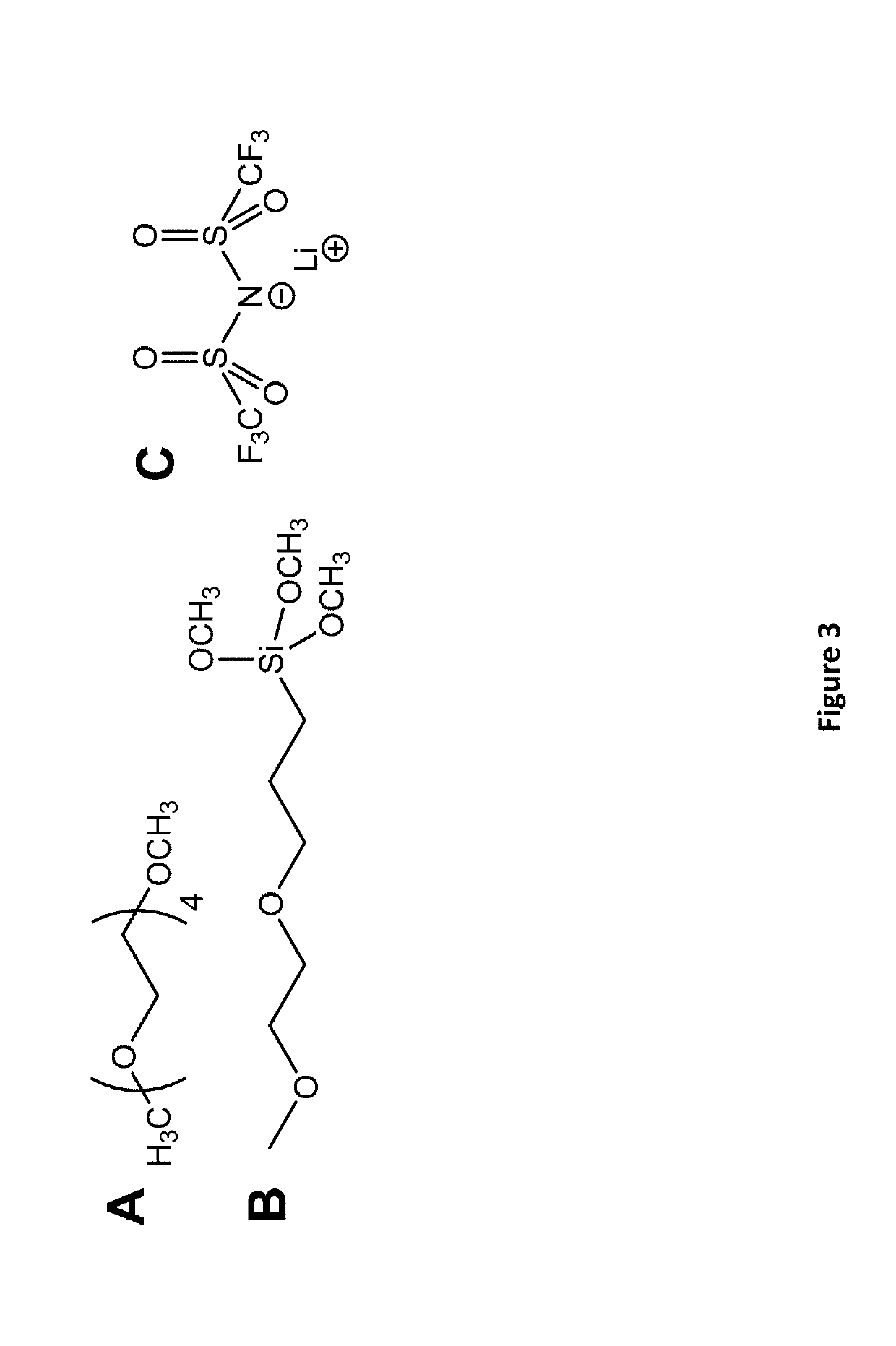
[0065]Conductivity tests show that low interfacial resistance (high conductivities) can be obtained when the LICGC-SiO2 is silanated with PEG-silane / LiTFSI (O / Li=12 / 1) or infused with mixtures of G4 / LiTFSI (O / Li=4 / 1). The area of each sample was kept at 0.25 cm2. The conductivity of the pure LICGC was tested between stainless steel (SS) electrodes, using carbon paste to make electrical contact. Temperature dependent Z″ vs Z′ impedance plots from the EIS data (FIG. 7) are similar to those reported in the literature [Zhu et al., 2016, Journal of Materials Chemistry A, 4, (9), 3253-3266; Richards et al., 2016, Chemistry of Materials, 28, (1), 266-273]. At low temperature there are two distinguishable semicircles. The one at higher frequency (to the left) is attributed to the grain boundary resistance, with the bulk resistance the intercept at high frequency (125Ω). The semicircle at lower frequency (to right) is attributed to the resistance between the LICGC ...


PUM

PropertyMeasurementUnit
conductivityaaaaaaaaaa
thicknessesaaaaaaaaaa
thicknessaaaaaaaaaa

Abstract

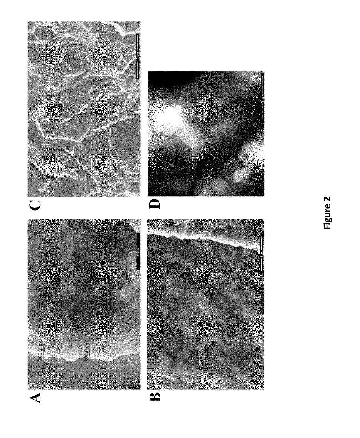
The invention provides a novel ceramic-metal oxide-polymer composite material. A functionalized metal oxide nanolayer coating can be bonded between LICGCs and polymers / oligomers, which protects the LICGC from corrosion, has a low interfacial resistance to Li+ migration, and can be a SIC. Hybrid ceramic-polymer electrolytes were formed by engineering the interface between a LICGC and a polymer, polyethylene oxide (PEO), by sputter coating a 200 nm thick SiO2 layer onto a lithium ion conducting glass ceramic (LICGC) and silanating the SiO2 with a functionalized PEG in the presence of LiTFSI. A low interfacial resistance (Rinterfacial) was measured, the same as that obtained for a SiO2 interface soaked with liquid tetraglyme / LiTFSI. The pegylated SiO2 interface (unlike the tetraglyme / LiTFSI interface) protected the LICGC from corrosion by Li0 metal. The (PEG-LiTFSI)-SiO2-LICGC could be bonded with polyethylene oxide / LiTFSI. This procedure provides a general method to bond other LICGCs to PEO-based polymers, and to incorporate other functionalities such as single ion conductivity into the interface via the incorporation of coupling agents with pendant anions.

Description

CROSS-REFERENCE TO RELATED APPLICATIONS[0001]The present application claims priority from U.S. Provisional Patent Application No. 62 / 406,248, filed on Oct. 10, 2016, which is incorporated by reference herein in its entirety.STATEMENT REGARDING FEDERALLY SPONSORED RESEARCH OR DEVELOPMENT[0002]This invention was made with government support under Grant Nos. DMR 1207221 and CBET 143781, awarded by the National Science Foundation. The government has certain rights in the invention.BACKGROUND OF THE INVENTION[0003]There is a strong drive for safer lithium ion batteries, as current technology relies upon flammable liquid electrolytes, which occasionally cause LIBs to ignite or explode, causing severe damage, injury, or death. Therefore, solid electrolytes with reduced flammability are a major goal in battery research. Ceramic electrolytes have high ionic conductivity (σ) and lithium ion transference numbers (tLi+→1), the fraction of the charge carried by the Li+, making them single ion co...

Claims


Application Information

Patent Timeline
Patent Type & Authority Applications(United States)
IPC IPC(8): H01M2/16H01M2/14C04B41/00C04B41/50C04B41/52C04B41/48C04B41/89H01M50/406
CPCH01M10/0525C04B41/5031H01M2/145C04B41/4861C04B41/009C04B41/522C04B41/5035H01M2/166C04B41/4896C04B41/89C08K9/02C08K9/06C08K3/36C08K3/22H01M50/446H01M50/406
Inventor WUNDER, STEPHANIEZDILLA, MIKECHINNAM, PARAMESWARA RAO
Owner TEMPLE UNIVERSITY
Learn More