Solid polymer electrolyte and method of preparation

a polymer electrolyte and solid-state technology, applied in the direction of wound/folded electrode electrodes, non-aqueous electrolyte cells, sustainable manufacturing/processing, etc., can solve the problems of low ambient temperature ionic conductivity of such highly branched peo, inability to successfully develop room temperature spe-based batteries, and inability to reduce the ionic conductivity at certain temperature, so as to reduce the ionic conductivity of the resulting ipn sp

Inactive Publication Date: 2003-09-25
OH BOOKEUN +3
View PDF49 Cites 58 Cited by
  • Summary
  • Abstract
  • Description
  • Claims
  • Application Information

AI Technical Summary

Benefits of technology

[0009] A primary objective of the present invention is to provide an IPN SPE having increased room temperature ionic conductivity with chemical and electrochemical stability.
[0010] Another object of the invention is to provide a thin IPN SPE with reduced bulk impedance and excellent mechanical strength.

Problems solved by technology

Up to now the key impediment to the successful development of such a polymer cell for room temperature operation is the low ionic conductivity of the solid polymer electrolyte.
All attempts in this program to successfully develop a room temperature SPE based battery were unsuccessful because of the low ionic conductivity at room temperature of PEO based electrolyte using the lithium trifluoromethane sulfonyl imide [LiN(CF.sub.3SO.sub.3), LiTFSI] salt ("TFSI").
Low molecular poly(ethylene oxide-dialkyl ether compounds) can contribute to increased room temperature ionic conductivity of SPE, but they still have crystallization problem which decrease the ionic conductivity at certain temperature.
However, the ionic conductivity of such highly branched PEO is still low at ambient temperature.
Simple crystalline PEO may meet that requirement, but most of modified PEO based SPEs are not strong enough for real cell applications.
Crosslinked SPEs were developed as a solution, but the crosslinking reaction restricts polymer chain mobility that is needed for lithium ion transport.
The use of volatile solvents to make the SPEs increase the processing steps such as evaporation and recovery, increase costs of manufacture, and may pose serious environmental and safety issues.
This crosslinking approach results in a significantly reduced flexibility of siloxane with PEO polymer.

Method used


Image

  • Solid polymer electrolyte and method of preparation
  • Solid polymer electrolyte and method of preparation
  • Solid polymer electrolyte and method of preparation

Examples


examples 1-2

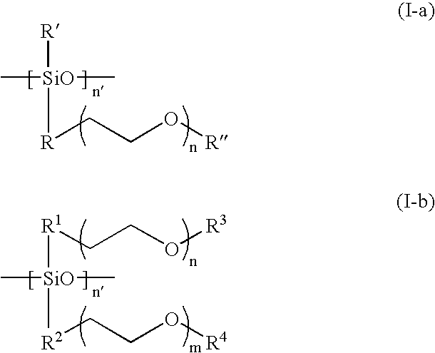
[0044] For Examples 1-2, Li(CF.sub.3SO.sub.2).sub.2N (LiTFSI) salt was dissolved in a branched type siloxane polymer (n=7.2, R' and R" are methyl groups in formula I-a, M.sub.n=ca. 2000), poly(ethylene glycol) ethyl ether methacrylate (PEGEEMA) with average M.sub.n of ca. 246 and poly(ethylene glycol-600) dimethacrylate (PEGDMA600) with average M.sub.n of ca. 740 mixture. After clear dissolution of LiTFSI, benzoyl peroxide was added into the resulting solution and mixed to get a precursor solution for IPN type SPE. The composition of Examples 1-2 is shown in Table 1. Porous polycarbonate membrane is used as a supporter for the IPN SPEs. The ionic conductivity of the IPN polymer electrolytes at temperatures ranging from 25 to 80.degree. C. were measured from the ac impedance curves of 2030 button cells assembled by sandwiching the IPN SPE between two stainless steel discs with a frequency range from 1 MHz to 10 Hz. The result is shown in FIG. 1. Both of two IPN SPEs show high ionic c...

example 3

[0045] FIG. 6 is a trace of current density vs. potential during repeated voltage sweep of a cell made according to this invention at a scan rate of 5 mV / sec. It shows the electrochemical stability with 60 wt % branched type siloxane polymer (n=7.2, R' and R" are methyl groups in formula I-a infra), 30 wt % poly(ethylene glycol) ethyl ether methacrylate, 10 wt % of poly(ethylene glycol-600) dimethacrylate and Li(CF.sub.3SO.sub.2).sub.-2N. More specifically, it shows the electrochemical stability of IPN SPE with the same composition as Example 1. Polypropylene melt-blown type nonwoven separator material is used as a supporter for this IPN SPE. The electrochemical stability window of this IPN polymer electrolyte was determined by cyclic voltammetry with a 2030 button cell assembled by sandwiching this IPN SPE between a stainless steel disc as a working electrode and lithium metal disc as the counter and reference electrodes. This IPN SPE shows an excellent electrochemical stability wi...

example 7

Lithium Ion Transference Number

[0048] Li metal / IPN SPE of Example 2 / Li metal cell was assembled for the measurement of Li ion transference number t.sub.+. A 2030 button cell was used. A potentiostatic curve (FIG. 8a) was measured by using dc polarization method and the change of the cell impedance before and after polarization (FIG. 8b) was examined by using Schlumberger model 1255 frequency response analyzer connected to Schlumberger model 1286 electrochemical interface and EG&G PAR 273 potentiostat. The Li transference number was given by following equation suggested by K.M. Abraham et al., Chem. Mater., 9, 1978 (1997): 1 t + =I s R b s ( V - I oR i o) I o R b o ( V - I sR i s)

[0049] Wherein V is the dc potential applied across the symmetric cell, o and s represent the initial and steady state, and b and i represent bulk and interfacial resistance of the electrolyte.

[0050] Lithium transference number of IPN SPE of Example 2 was approximately 0.29, which is much improved over that ...


PUM

PropertyMeasurementUnit
conductivityaaaaaaaaaa
melting pointaaaaaaaaaa
ionic conductivitiesaaaaaaaaaa

Abstract

Disclosed is an improved solid electrolyte made of an interpenetrating network type solid polymer comprised of two compatible phases: a crosslinked polymer for mechanical strength and chemical stability, and an ionic conducting phase. The highly branched siloxane polymer of the present invention has one or more poly(ethylene oxide) ("PEO") groups as a side chain. The PEO group is directly grafted to silicon atoms in the siloxane polymer. This kind of branched type siloxane polymer is stably anchored in the network structure and provides continuous conducting paths in all directions throughout the IPN solid polymer electrolyte. Also disclosed is a method of making an electrochemical cell incorporating the electrolyte. A cell made accordingly has an extremely high cycle life and electrochemical stability.

Description

REFERENCE TO PRIOR FILED APPLICATIONS[0002] None[0003] The present invention relates to the composition and assembly methods of solid polymer electrolytes and their use in electrochemical cells, especially in lithium ion rechargeable batteries. The invention particularly relates to interpenetrating network type solid polymer electrolyte systems with highly ionic conductivity poly(ethylene oxide) ("PEO") grafted siloxane polymers as a conducting phase.[0004] Efforts to develop electrochemical cells having PEO based solid electrolyte systems have continued since about 1973. (M. B. Armand, Fast Ion Transport in Solids, North Holland, Amsterdam, p665, (1973); D. E. Fenton et al., Polymer, 14, 589 (1973)). The main advantages of such a cell system are multifold: (1) very high energy density; (2) potential for excellent electrolyte stability; (3) the ability to be configured in nearly any shape since it contains no liquid; (4) the opportunity to be very inexpensive; (5) inherent safety ch...

Claims


Application Information

Patent Timeline
Patent Type & Authority Applications(United States)
IPC IPC(8): C08L83/12H01B1/12H01M6/18H01M10/04H01M10/052H01M10/0525H01M10/0565H01M10/0585H01M10/0587H01M10/36H01M10/38
CPCC08L83/12H01B1/122H01M6/181H01M10/0431H01M10/052H01M10/0525Y10T29/49115H01M10/0585H01M10/0587H01M10/38H01M2300/0082Y02E60/122H01M10/0565Y02E60/10Y02P70/50
Inventor OH, BOOKEUNAMINE, KHALILHYUNG, YOO-EUPVISSERS, DONALD R.
Owner OH BOOKEUN
Why Eureka
Try Eureka