
Compressor provided with safety relief valve assembly

a technology of safety relief valve and compression valve, which is applied in the direction of pump control, pump parameters, pump components, etc., can solve the problems of white smoke and failure of engagement, and achieve the effects of excellent reliability, excellent productivity and low cos

Active Publication Date: 2019-10-31
VALEO NORTH AMERICA
View PDF3 Cites 0 Cited by
  • Summary
  • Abstract
  • Description
  • Claims
  • Application Information

AI Technical Summary

Benefits of technology

The present invention provides a compressor with excellent productivity, durability, and safety. The compressor prevents inflammable components from leaking through a safety relief valve and causes other problems such as rotation failure, engagement failure, and white smoke. This is achieved by a blocking portion that prevents ejection of a working fluid containing lubricating oil in a specific direction. The blocking portion is integrated with the housing of the compressor and avoids the need for attachment and inspection processes, which improves efficiency and reliability. The blocking portion is preferably a plate member or a groove part which facilitates the capture of the working fluid and prevents it from diffusing too far. Overall, the present invention provides a safer and more effective compressor for use in various applications.

Problems solved by technology

However, when the working fluid is ejected to a specific direction in the engine room of a vehicle, troubles may occur such that the working fluid enters between the drive belt and the pulley for driving the compressor as well as other components such as an alternator to cause rotation failure or enters between the armature plate and the pulley to cause engagement failure.
Moreover, a trouble may occur such that the working fluid makes contact with the high-temperature components such as an exhaust manifold to cause white smoke.

Method used


Image

  • Compressor provided with safety relief valve assembly
  • Compressor provided with safety relief valve assembly
  • Compressor provided with safety relief valve assembly

Examples


Embodiment Construction

[0033]Various embodiments are described in detail below by using the drawings and taking a swash plate compressor as a specific example. However, the present invention is not limited to these embodiments but is limited only by the technical idea described in the claims, and includes all techniques subsumed under the claims.

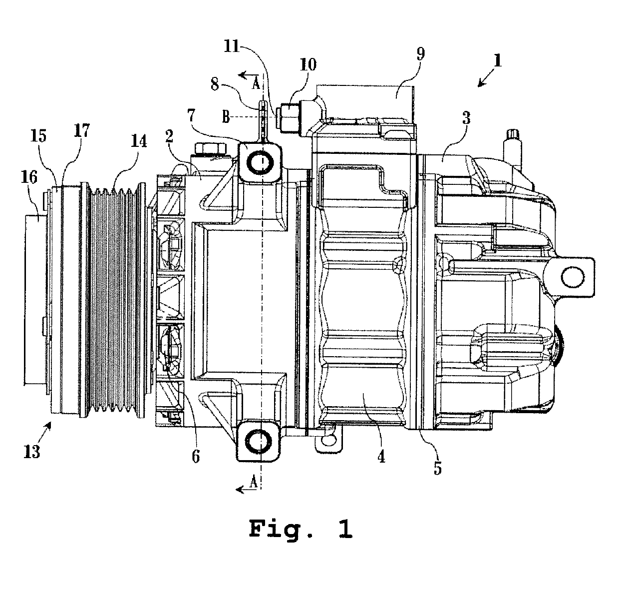
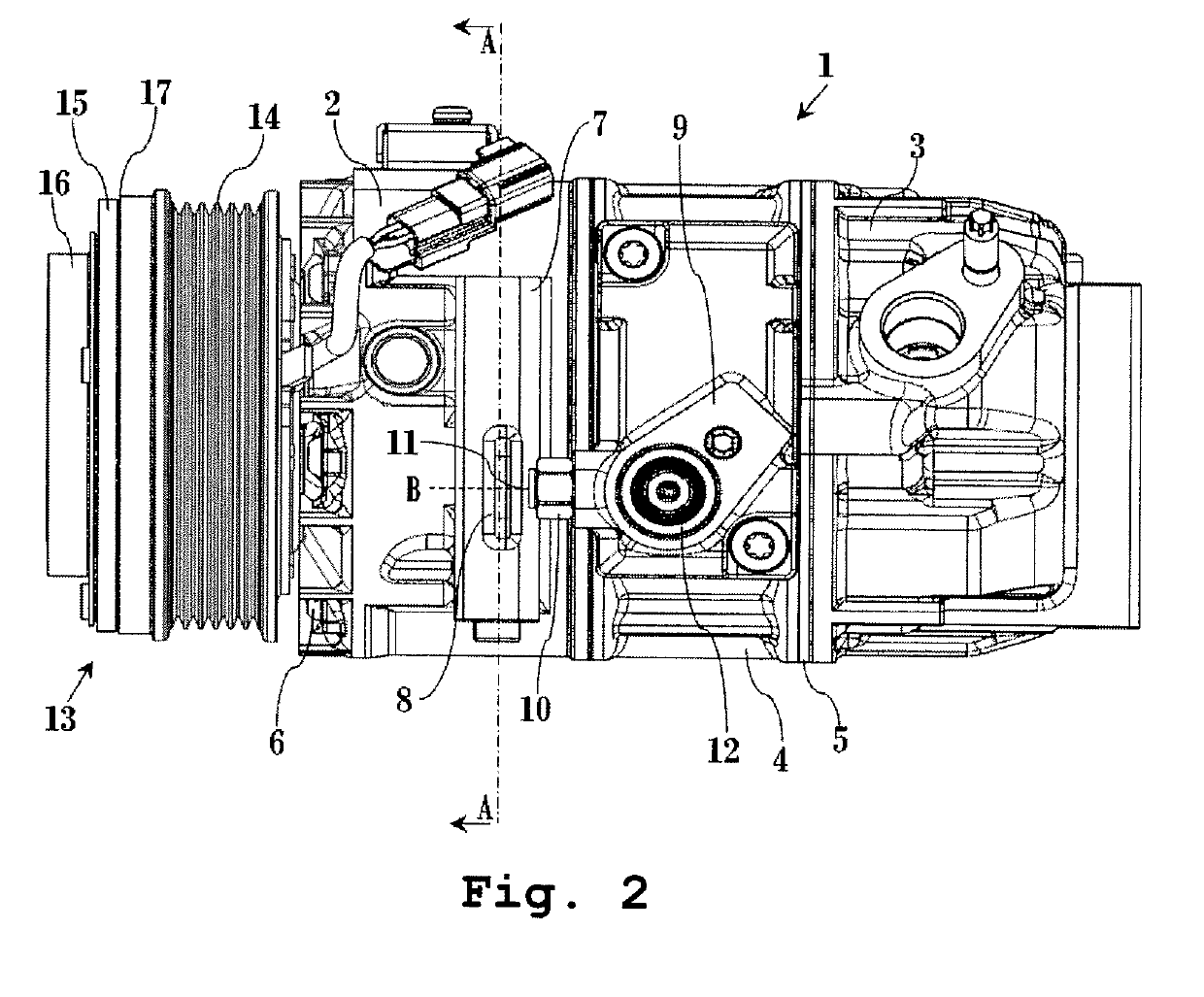
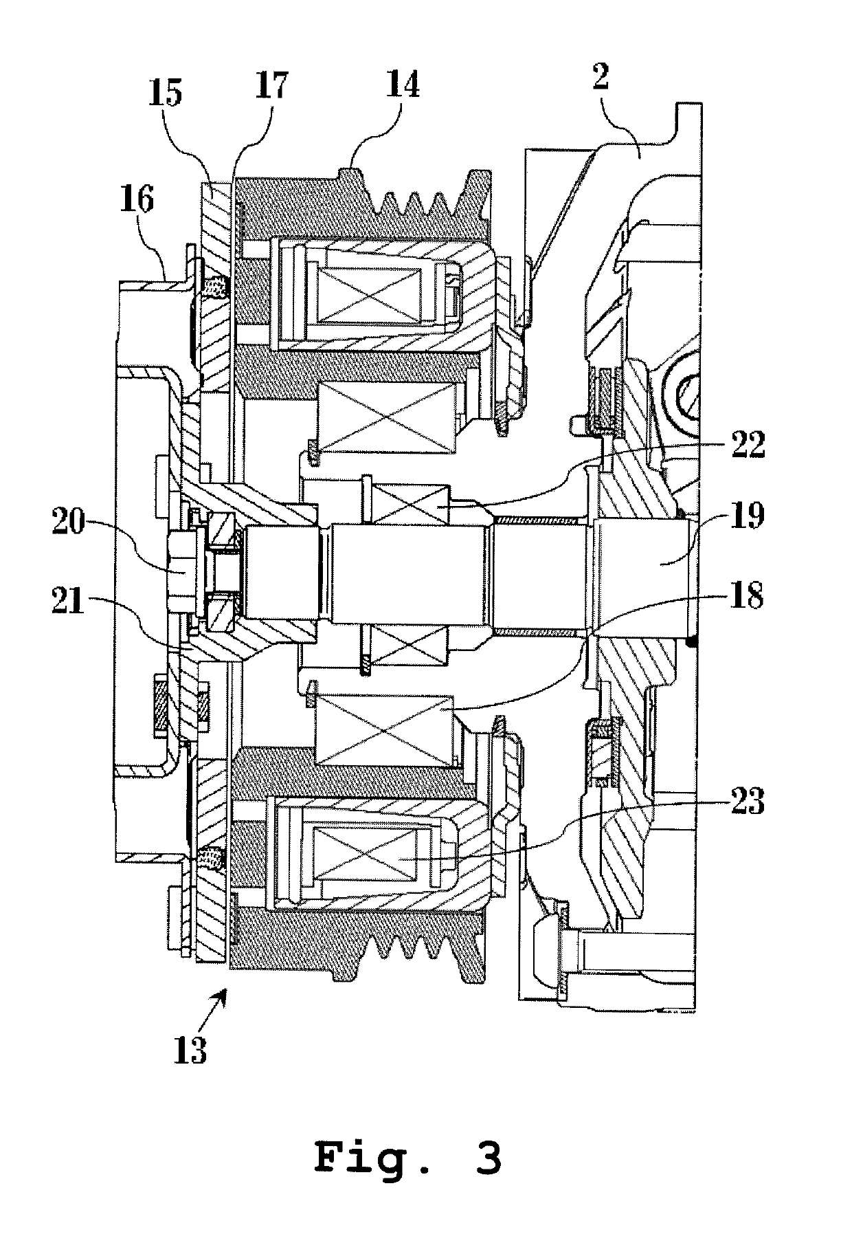
[0034]FIG. 1 is a schematic side view of a swash plate compressor 1 formed to have a plate member as a blocking portion 8 externally provided to a part of a compressor-attachment mount portion 7, according to one embodiment of the present invention, and FIG. 2 is a plan view thereof. FIG. 3 is a schematic sectional view of an electromagnetic clutch 13 of the swash plate compressor 1 depicted in FIG. 1 and FIG. 2, the electromagnetic clutch 13 configured of a pulley 14, a field coil 23, and an armature assembly 16. FIG. 4 is a schematic sectional view of a portion of the swash plate compressor 1 depicted in FIG. 1 and FIG. 2 near a safety relief valve 10 and the bl...


PUM


Abstract

A compressor of the present invention has a blocking portion for preventing a refrigerant containing an inflammable component such as lubricating oil ejected from an ejection port of a safety relief valve from being ejected to a specific direction where a drive belt, an electromagnetic clutch, an exhaust manifold, and placed. The blocking portion is not separately attached but is integrally formed with a housing member by using the same material as that thereof, and is disposed on a line in an ejection direction of the ejection port. The present invention can provide a compressor excellent in productivity, durability, and safety without increasing the number of manufacturing processes or causing, for example, rotation failure of the drive belt and a pulley for driving the compressor and its auxiliaries and an occurrence of white smoke due to a contact between the exhaust manifold at high temperatures and the refrigerant.

Description

BACKGROUND OF THE INVENTION1. Field of the Invention[0001]The present invention relates to a compressor having a component disposed to block a refrigerant containing lubricating oil ejected from a safety relief valve included in a compressor for use in an automotive air conditioning system.2. Description of the Related Art[0002]A compressor generally has a safety relief valve which discharges high-pressure inner fluid to the outside to mitigate internal pressure when the internal pressure exceeds a predetermined value. In this safety relief valve, particularly in the case of a compressor using an internal-combustion engine in an automotive air conditioning system, a refrigerant containing an inflammable component such as lubricating oil ejected from the safety relief valve of the compressor may enter a space between a drive belt and a pulley for driving the compressor and its auxiliaries to cause rotation failure or between an armature plate and the pulley configuring an armature as...

Claims


Application Information

Patent Timeline
IPC IPC(8): F04B49/03F04B49/22F04B43/00F04B39/10
CPCF04B43/009F04B2201/06F04B39/10F04B49/03F04B49/22
Inventor JACKSON, ROBERTCHUANG, YEI-HSINE
Owner VALEO NORTH AMERICA
Learn More