Pumps and hardware for organ-on-chip platforms

a chip platform and pump technology, applied in the field of microfluidic devices, can solve the problems of lack of clinical efficacy, toxicity, limited pharmacokinetic studies in multi-mps platforms, etc., and achieve the effects of maintaining fluidic sterility, low energy consumption, and constant displacement strok

Active Publication Date: 2019-11-07
MASSACHUSETTS INST OF TECH
View PDF5 Cites 2 Cited by
  • Summary
  • Abstract
  • Description
  • Claims
  • Application Information

AI Technical Summary

Benefits of technology

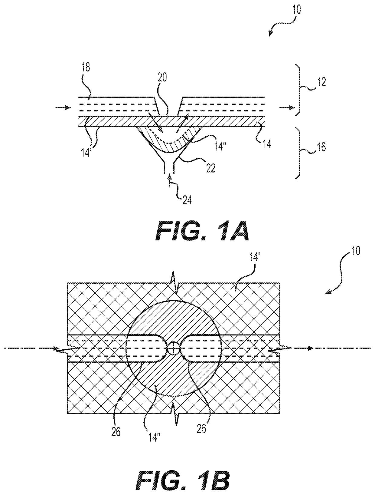
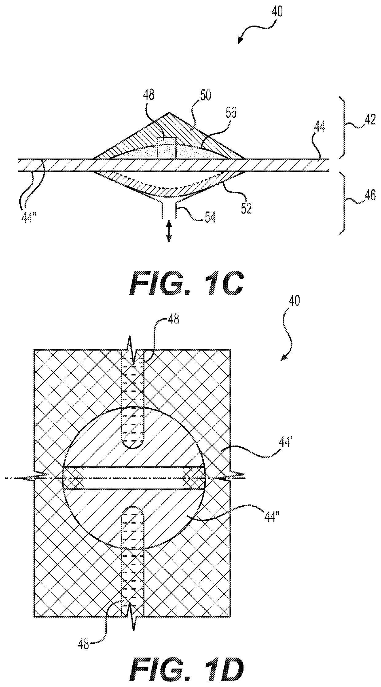
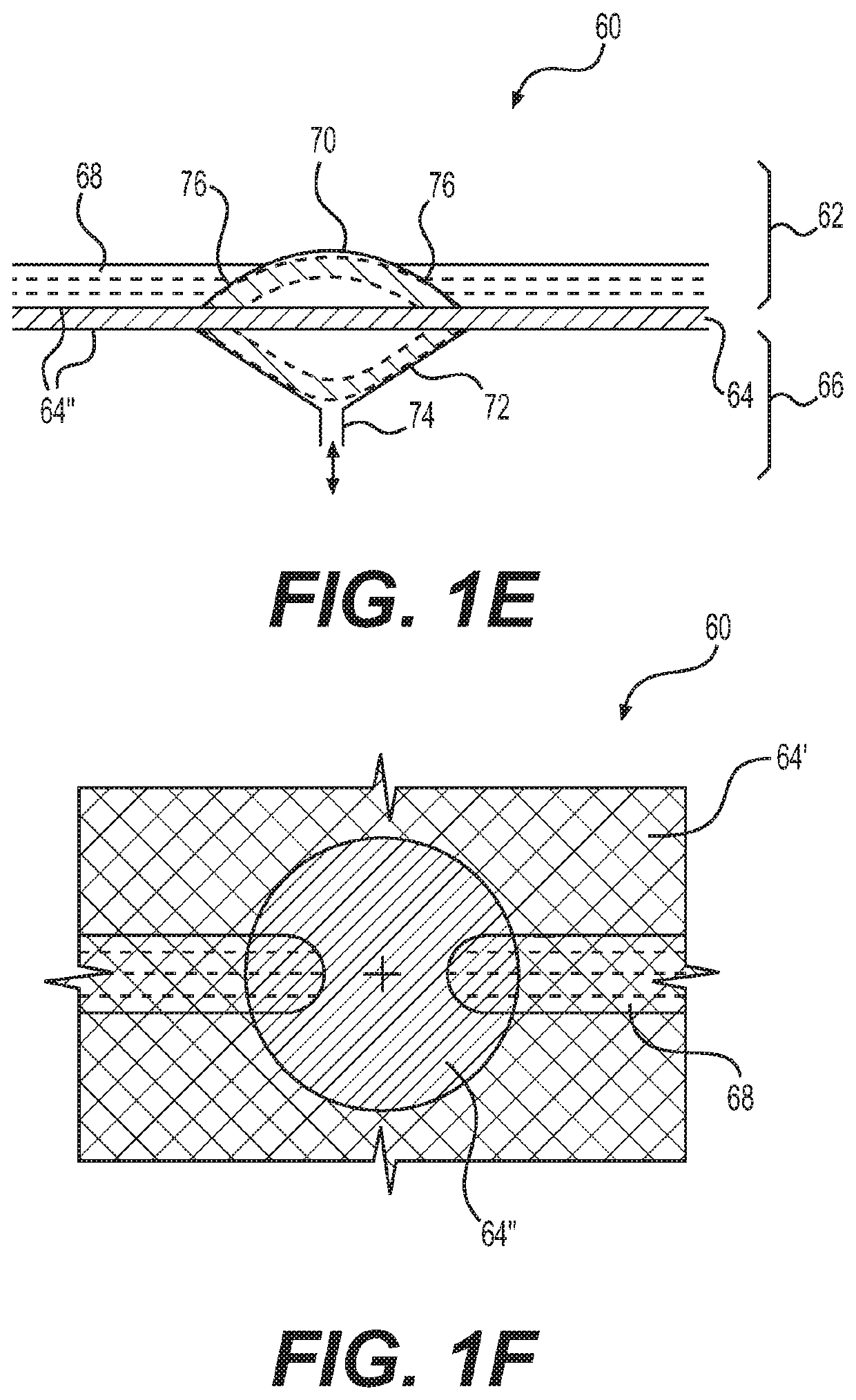
[0011]On-platform electromagnetic (EM) pumps for use with the organ-on-chip platforms have been developed. The EM pump uses electrical energy, which may be supplied by a battery, making the pump portable, or plugged into an Alternating Current (AC) 110 volt circuit. The EM pump may use a linear EM actuator having a low energy consumption. The EM pump may use a teeter-totter EM actuator having a low energy consumption. The actuator's low energy consumption is achieved by a latching design which requires only a short pulse of energy to switch its state, flux biasing where the magnetic flux from the winding current adds and subtracts to the magnetic flux from the permanent magnet on either side, and by using springs that store some of the actuator kinetic energy, which is then recovered in the reverse stroke. This further reduces the energy consumption of the actuator.
[0012]Also provided are injection-molded, single-use platforms with onboard diaphragm micro-pumps and various valve and pump geometries. The EM actuators easily integrate with these platforms, demonstrating pumping at a constant flowrate, no measurable temperature rise, and valve sealing against varying back-pressure.
[0018]Also described are methods for actuating fluid in a fluidic device. The methods typically include contacting the fluid with the diaphragm, displacing volume by moving the diaphragm with the EM actuator. The diaphragm ensures physical separation of the fluidic and the actuation side thereby maintaining fluidic sterility. The actuator typically provides a constant force sufficient to deflect the diaphragm against varying fluid back-pressure to stop fluid flow. The actuator generally operates with low energy consumption and maintains constant displacement stroke with varying back-pressure. The actuator operates without substantial increase in actuator or fluid temperature.

Problems solved by technology

However, lack of clinical efficacy, rather than toxicity, was identified as the leading cause of drug attrition in Phase II and III clinical trials (the most costly stage) (Kubinyi H, Nat Rev Drug Discov 2(8):665-668 (2003); Cook D, et al.
While toxicology and pharmacodynamic studies are common applications, pharmacokinetic studies have been limited in multi-MPS platforms.
Other practical limitations in the design and fabrication of the hardware also significantly reduce the robustness, long-term reliability, and compatibility of customization in existing multi-MPS devices.
Poor hardware designs and constructs often result in a poor control or lack of control on the directionality of fluid among wells (inter-well directionality) and within-well recirculation, leaving some wells dry due to breakage of fluid flow, the syphoning effect, and / or evaporation.
Media depletion and waste removal at near-physiological scales often require single-pass media flow, making it difficult or impossible to study slow-clearing drugs, effects of drug metabolites, and inter-MPS communications.
Removable inserts to fit into the wells of multi-MPS devices may be desirable in culturing some tissues, but their compatibility with fluid in-flow to support perfusion of cultures has been difficult to achieve.
These pumps require significant effort in setup and depend on external pressure and vacuum sources.
These platforms require significant effort in setup, which is especially challenging given the sterility requirements during and after assembly.

Method used


Image

  • Pumps and hardware for organ-on-chip platforms
  • Pumps and hardware for organ-on-chip platforms
  • Pumps and hardware for organ-on-chip platforms

Examples


example 1

Polymer Materials and Chamber Geometries for Forming a Micro-Pump

[0300]Generally, polymer manufacturing is a variable process in which it is challenging to achieve tight consistency in the composition at reasonable prices, especially for low volume manufacturing. In the existing pumps, polyurethane (PU) diaphragms were used, the physical properties of which were found to be varying stock to stock for the same specification, from the same manufacturer.

[0301]Therefore, based on the recommendation by the supplier, a larger lot quantity was purchased and was used to cut the diaphragms for the platforms to maintain assembly to assembly consistency.

[0302]It is important to limit the working range to within the linear elastic regime of the diaphragm material so that the diaphragm returns back to its initial position every actuation. Otherwise, if the material yields, it will have some permanent deformation set into the diaphragm which will cause it to slack leading to non-deterministic vol...

example 2

and Testing the Deflection Behavior of Diaphragms

[0308]Materials and Methods

[0309]A model may be used to predict the diaphragm deflection for a given pressure difference across it, with a bonded (fully clamped) boundary condition at the edges. Then the pressure at which the diaphragm makes contact with the wall for the pumps and valves can be predicted. Diaphragm deflections can be categorized into three categories.

[0310]The thickness of the diaphragm is fixed (0.065-0.075 mm), the range of deflection depths (0.075-0.150 mm) is fixed and the range of pressures is also fixed (±20-±100 kPa(g)). Therefore, the problem is to find the feasible range of diameters which will work for these parameters. The diaphragm parameters used for modeling are given in Table 6.

TABLE 6Diaphragm physical parameters used for modeling. Detailsof measurement of measured values are given in Example 3.ParameterSymbolValueUnitsYoung's modulusE1300-1500MPa(measured)DensityP940kg / m3Poisson's ratioν0.41—Yield str...

example 3

nt of Uni-Axial Young's Modulus of the COC Diaphragm and the Volume Displaced Vs. Actuation Pressure

[0333]Materials and Methods

[0334]The physical parameters of the diaphragm were acquired. Since the physical properties such as Young's modulus and the yield stress can have a large variation manufacturing lot-to-lot, these properties were measured. The Young's modulus of the diaphragm was measured as per the ASTM D882-12 standard (ASTM International, “ASTM D882: Standard Test Method for Tensile Properties of Thin Plastic Sheeting,” p. 12, 2012). The Young's modulus was measured for multiple trials and found to be in the range of 1300-1500 MPa. FIGS. 19A and 19B show the plots of data obtained for one of the tests. FIG. 19A shows calculation of Young's modulus with a linear fit line for the linear regime. The slope is the Young's modulus and the value is found to be 1322 MPa. In the regions of lower strain, the slope is slightly higher with a maximum value of 1500 MPa. Thus, the Young'...


PUM

PropertyMeasurementUnit
diametersaaaaaaaaaa
pressureaaaaaaaaaa
stress-strain curveaaaaaaaaaa

Abstract

On-platform pumps provide greater flexibility and design freedom and are a key feature of organs-on-chip platforms. On-platform electromagnetic (EM) pumps have been developed for use with the organ-on-chip platforms. The EM pump uses electrical energy, which may be supplied by a battery, making the pump portable. The EM pump uses an EM actuator having a low energy consumption. The actuator's low energy consumption is achieved by a latching design which requires only a short pulse of energy to switch its state and where springs store some of the actuator kinetic energy, which is then recovered in the reverse stroke. This further reduces the energy consumption of the actuator. Also provided are injection-molded, single-use platforms with onboard diaphragm micro-pumps and various valve and pump geometries. The EM actuators easily integrate with these platforms, demonstrating pumping at a constant flowrate, no measurable temperature rise, and valve sealing against varying back-pressure.

Description

CROSS-REFERENCE TO RELATED APPLICATIONS[0001]This application claims the benefit of and priority to U.S. Provisional Application No. 62 / 665,348 filed May 1, 2018, which is incorporated herein by reference in its entirety.FIELD OF THE INVENTION[0002]The invention is generally directed to microfluidic devices for cell and tissue culture and to the subcomponents of the microfluidic devices.BACKGROUND OF THE INVENTION[0003]Recent advances in cell biology, microfabrication and microfluidics have enabled the development of microengineered models of the functional units of human organs, known as organs-on-a-chip (OOC) that could provide the basis for preclinical assays with greater predictive power. Early embodiments have been described and commercialized. For example, U.S. Pat. No. 6,197,575 to Griffith, et al., describes a micromatrix and a perfusion assembly suitable for seeding, attachment, and culture of complex hierarchical tissue or organ structures. U.S. Pat. No. 8,318,479 to Inman...

Claims


Application Information

Patent Timeline
Patent Type & Authority Applications(United States)
IPC IPC(8): C12M3/00B01L3/00B01L9/00C12M3/06C12M1/00F04B43/04
CPCB01L2400/0415B01L2300/123B01L9/527F04B43/043B01L3/502707B01L3/502715C12M29/00B01L2200/027B01L2200/10B01L3/502753C12M23/16B01L2200/025B01L3/50273B01L2400/043C12M21/08H01F7/122H01F7/14H01F7/1646F04B43/14
Inventor BHUSHAN, BRIJ MOHANRATHBONE, DANIEL R.TRUMPER, DAVID L.NOH, MINKYUNYOON, JUN YOUNG
Owner MASSACHUSETTS INST OF TECH
Why Eureka
Try Eureka